Rei Vilo's fischertechnik Corner
  • About
  • Blog
  • Reviews
    • How to Start?
    • Controllers >
      • Robotics TXT
      • TXT 4.0 Controller
      • Bluetooth Smart Beginner Set
      • Interface Boards for fischertechnik Models
      • Didacta Advance Pi-F5 interface board
    • Sets >
      • Technical Revolutions Set
      • Pneumatic Power Set
      • Automation Robots Set
      • Electro-Pneumatic Set
      • Starter Set for micro:bit
      • Bluetooth Smart Beginner Set
      • Robotics TXT Smart Home Set
    • Exploring the Lego World >
      • Purchasing
      • Unboxing
      • Installing
      • Building
      • Programming
      • Connecting
      • Playing
      • Expanding
      • Concluding
  • Models
    • Back to the 70's
    • Micro Models
    • New Magasin >
      • Magasin releases 1, 2 and 3
      • Long X-Axis
      • Moving Desk And Y-Axis
      • Compressed Air And Vacuum For Z-Axis
      • Pictures
      • Specifications
    • Power Saving White LED
    • Flipper with I²C LCD Panel
    • Celebrating 50 Years!
    • ft Convention 2013
    • ft Convention 2014
  • Sensors
    • Interfacing an Arduino to a Robo TX Controller >
      • Analog Interface
      • Digital Interface
      • I²C Interface
    • Standard Sensors >
      • Playing With Accelerometers
      • Proximity Sensor
      • Pressure Sensor
    • Advanced Sensors >
      • Industrial Colour Reader
      • Stepper Motor Controller
      • DC-Motor with Quadrature Encoder Controller
    • smartDevices >
      • smartColours
      • smartRFID
      • smartLED
      • smartHub
      • smartControls
      • smartMeter
      • smartCamera
      • smartNewCamera
      • smartWiFi
      • smartBLE
      • smartNode
      • smartIMU
  • RoboPro
    • Value Operations >
      • Min and Max Functions
      • Signal Management With Median
      • Modulo Function
      • Map Function
    • Standard Modules >
      • Software Managed Compressor
      • Self-Calibrated Colour-Reader
      • Standard Conveyor Belt Routine
      • Management Panel
      • Encoder-Motor Position Management
    • Variable Types >
      • CSV List Management
      • Queue Function
    • Program Structures >
      • Parallel Processing
      • Multi-Tasking End Management Procedure
    • Tutorials >
      • Setting Bluetooth LAN with Multiple TX-Cs
      • Dealing with Very Large Models >
        • Getting a General View
        • Defining User's Functions
        • Elaborating the Modelisation
        • Defining the Processes
        • Setting the Messages
        • Going Further
        • References
      • Program Error 2 Message
  • I²C
    • How to Connect an I²C Device to the Robo TX?
    • How to Connect an I²C Device to the Robotics TXT?
    • How to Manage an I²C Device?
    • How to Use an I²C Driver?
    • List of I²C Drivers for Sensors >
      • I²C Real Time Clock DS1307
      • I²C LCD screen 4 lines of 20 characters LCD03
      • I²C Triple Axis Accelerometer ADXL345
      • I²C Red-Green-Blue LED BlinkM
      • I²C Two Axis Compass HMC6352
      • I²C Triple Axis Magnetometer HMC5843
      • I²C True Colour Sensor ADJD-S371
      • I²C Stepper Controller AMIS-30624
    • List of I²C Drivers for smartDevices >
      • I²C True Colours Smart Sensor smartColours
      • I²C RFID Smart Sensor smartRFID
      • I²C 4-Digit 7-Segment LED Display smartLED
      • I²C Screen With Touch and SD-Card smartControls
      • I²C Smart Sensor smartCamera
      • I²C Smart Sensor smartNewCamera
      • I²C Remote WiFi Interface smartWiFi​
      • I²C Remote Bluetooth Interface smartBLE​
      • I²C Remote Interface smartNode​
      • I²C New LCD Screen 4 x 20 characters smartLCD
      • I²C Inertial Measurement Unit smartIMU

X-Y Joystick Remote-Controlled Device

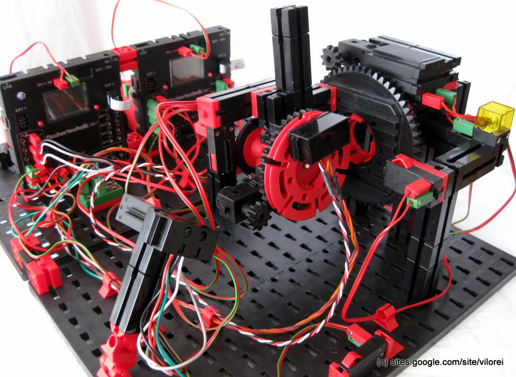
This second model is more complex:
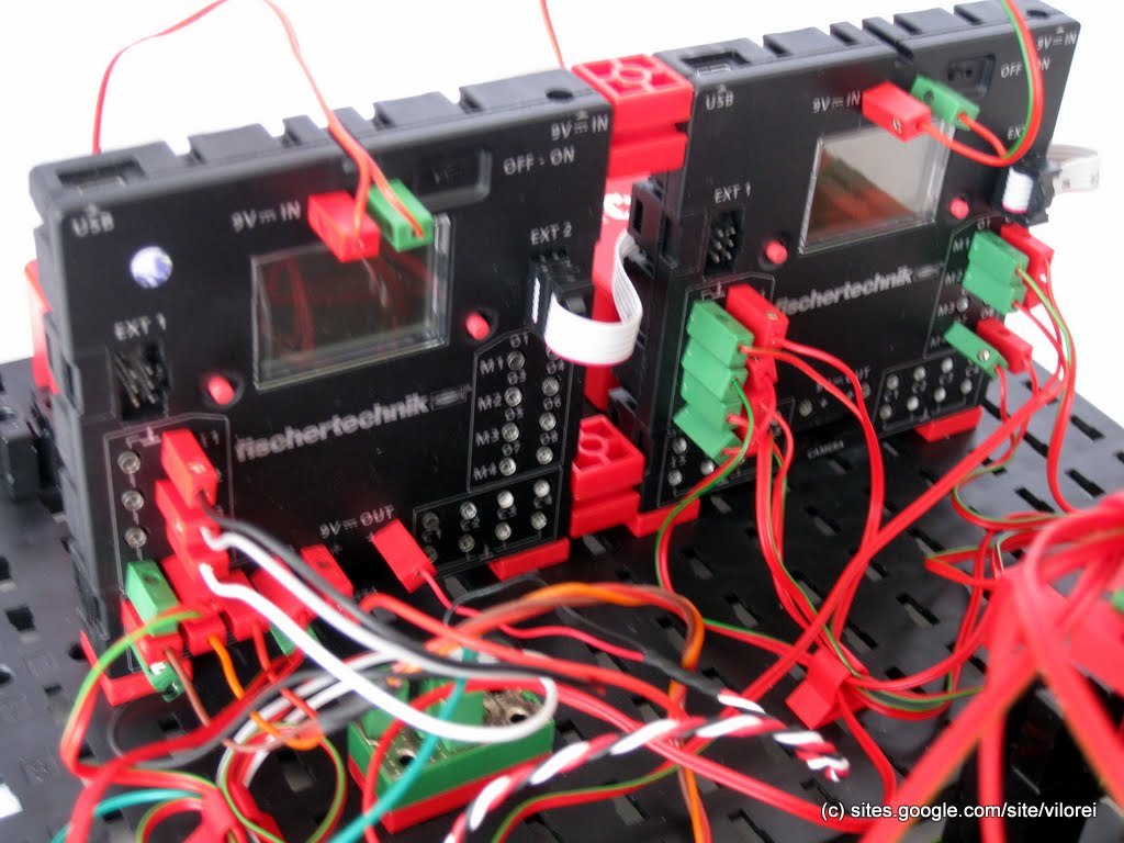
  • a first X-Y accelerometer is installed on top of the joystick,
  • a second accelerometer on a X-Y device is moved by two motors,
  • the goal is to replicate the angle from the joystick to the device.  
Picture

Hardware

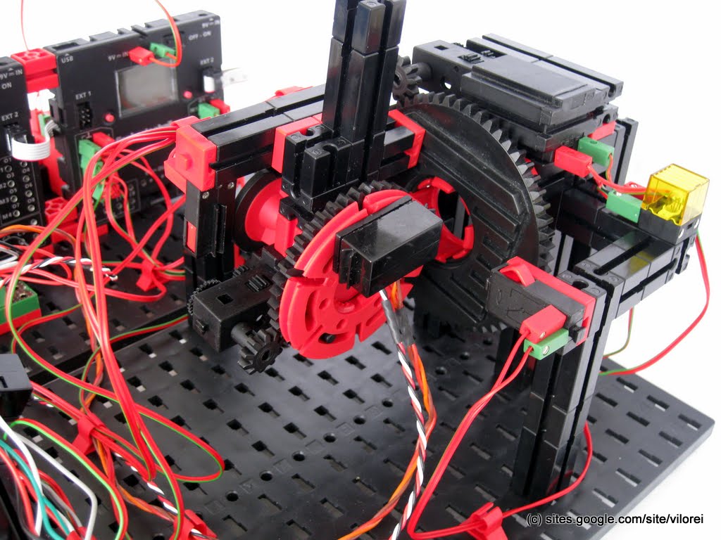
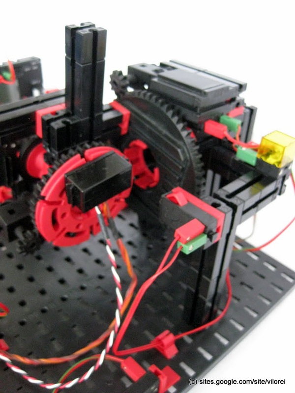
The device consists of two axis, each one with one motor and two end-of-course safety switches. 

The yellow lamp shows activity.
Picture

Below, 
  • The joystick includes the accelerometer and a trigger on top.
  • Detail of one axis with its motor.
  • The end-course contacts for safety.


Picture
Picture
Picture
Picture

Software

The software is based on the comparison between the values of the two accelerometers and commands the two motors.

It is pretty basic and relies on fuzzy logic with simple rules.

However, two TX-Cs are needed: each accelerometer requires 3 A/D inputs, and the device needs 4 end-of-course contacts for safety.
Picture

Download

The attached file is licensed under a Creative Commons Attribution-NonCommercial-ShareAlike 4.0 International License. 
ft_xy_joystick_command.zip
File Size: 64 kb
File Type: zip
Download File


Previous

Self-Positionning Horizontal Device

Next

Dynamic Propelled Horizontal Device
Powered by Create your own unique website with customizable templates.