Management Panel
|
After the release of my New Magasin model, I received many questions about the management panel.
Here are 5 options. |
|
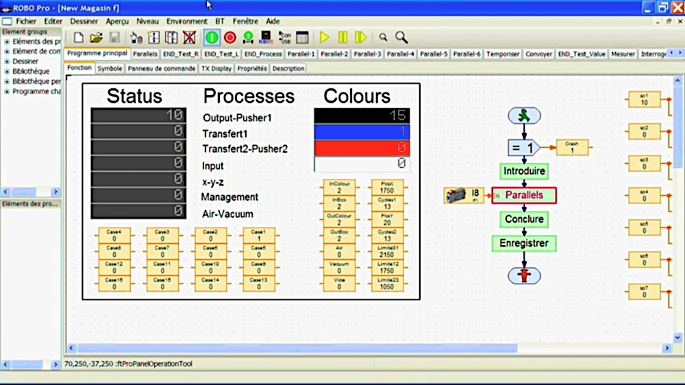
1. Standard
|
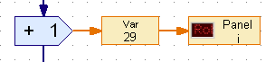
The standard uses the Var boxes and the Interface Test window to show values, inputs / sensors and outputs / actuators.
This option only works on debugging on-line mode. This option is great for debugging because it operates on the working area where the algorithm is, but the Var boxes could be difficult to read. |
|
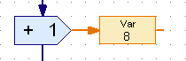
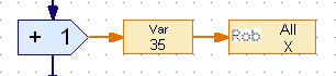
2. On the Working Area
|
Displays and buttons could be placed directly on the working area.
|
|
|
This option only works on debugging on-line mode.
This option is great for debugging because it operates on the working area where the algorithm is. It provides a better look. |
|
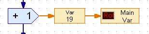
3. On the Command Panel
|
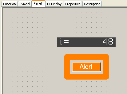
Robo Pro provides a specific Command Panel where displays and buttons can be placed.
|
|
|
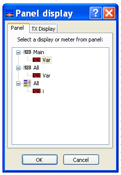
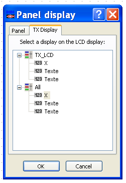
The option 3. Command Panel requires to choose the display or meter from the Panel pane on the Panel display setting.
The option 4. Robo TX LCD screen requires to choose the display or meter from the TX Display pane on the Panel display setting. |
|
|
This option only works on debugging on-line mode.
The working area with the algorithm is hidden, allowing a clean command panel. |
|
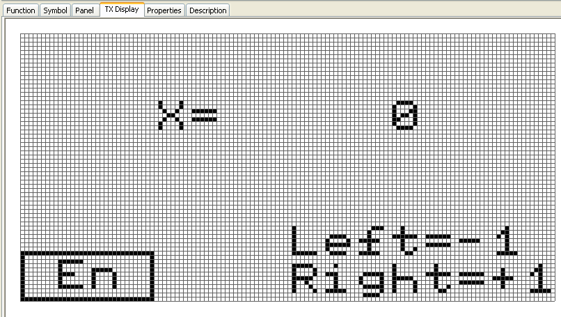
4. On the Robo TX LCD Screen
|
Another solution is to use the built-in LCD screen of the TX controller.
Here's how to program Robo Pro. the TX LCD screen is simulated. |
|
|
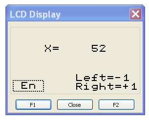
In debugging on-line mode, the LCD display is simulated in the window show right.
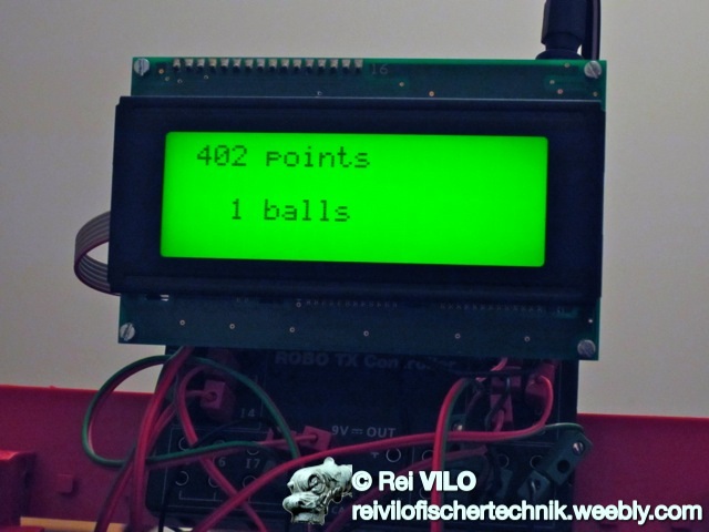
In compiled stand-alone mode, the Robo TX controller shows the values directly on its screen. Unfortunately, the screen isn't easy to read. |
|
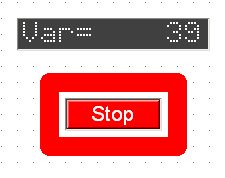
5. On an External I²C Display
|
This option requires an external display and the use of the I²C driver suited for it.
Learn more at I²C LCD screen 4 lines of 20 characters LCD03. Right, the I²C LCD panel for the electro-pneumatic flipper. |
|
Download
|
Download the driver with an example for RoboPro.
This file is under the Creative Commons Attribution-NonCommercial-ShareAlike 4.0 International License. |
| ||
