Rei Vilo's fischertechnik Corner
  • About
  • Blog
  • Reviews
    • How to Start?
    • Controllers >
      • Robotics TXT
      • TXT 4.0 Controller
      • Bluetooth Smart Beginner Set
      • Interface Boards for fischertechnik Models
      • Didacta Advance Pi-F5 interface board
    • Sets >
      • Technical Revolutions Set
      • Pneumatic Power Set
      • Automation Robots Set
      • Electro-Pneumatic Set
      • Starter Set for micro:bit
      • Bluetooth Smart Beginner Set
      • Robotics TXT Smart Home Set
    • Exploring the Lego World >
      • Purchasing
      • Unboxing
      • Installing
      • Building
      • Programming
      • Connecting
      • Playing
      • Expanding
      • Concluding
  • Models
    • Back to the 70's
    • Micro Models
    • New Magasin >
      • Magasin releases 1, 2 and 3
      • Long X-Axis
      • Moving Desk And Y-Axis
      • Compressed Air And Vacuum For Z-Axis
      • Pictures
      • Specifications
    • Power Saving White LED
    • Flipper with I²C LCD Panel
    • Celebrating 50 Years!
    • ft Convention 2013
    • ft Convention 2014
  • Sensors
    • Interfacing an Arduino to a Robo TX Controller >
      • Analog Interface
      • Digital Interface
      • I²C Interface
    • Standard Sensors >
      • Playing With Accelerometers
      • Proximity Sensor
      • Pressure Sensor
    • Advanced Sensors >
      • Industrial Colour Reader
      • Stepper Motor Controller
      • DC-Motor with Quadrature Encoder Controller
    • smartDevices >
      • smartColours
      • smartRFID
      • smartLED
      • smartHub
      • smartControls
      • smartMeter
      • smartCamera
      • smartNewCamera
      • smartWiFi
      • smartBLE
      • smartNode
      • smartIMU
  • RoboPro
    • Value Operations >
      • Min and Max Functions
      • Signal Management With Median
      • Modulo Function
      • Map Function
    • Standard Modules >
      • Software Managed Compressor
      • Self-Calibrated Colour-Reader
      • Standard Conveyor Belt Routine
      • Management Panel
      • Encoder-Motor Position Management
    • Variable Types >
      • CSV List Management
      • Queue Function
    • Program Structures >
      • Parallel Processing
      • Multi-Tasking End Management Procedure
    • Tutorials >
      • Setting Bluetooth LAN with Multiple TX-Cs
      • Dealing with Very Large Models >
        • Getting a General View
        • Defining User's Functions
        • Elaborating the Modelisation
        • Defining the Processes
        • Setting the Messages
        • Going Further
        • References
      • Program Error 2 Message
  • I²C
    • How to Connect an I²C Device to the Robo TX?
    • How to Connect an I²C Device to the Robotics TXT?
    • How to Manage an I²C Device?
    • How to Use an I²C Driver?
    • List of I²C Drivers for Sensors >
      • I²C Real Time Clock DS1307
      • I²C LCD screen 4 lines of 20 characters LCD03
      • I²C Triple Axis Accelerometer ADXL345
      • I²C Red-Green-Blue LED BlinkM
      • I²C Two Axis Compass HMC6352
      • I²C Triple Axis Magnetometer HMC5843
      • I²C True Colour Sensor ADJD-S371
      • I²C Stepper Controller AMIS-30624
    • List of I²C Drivers for smartDevices >
      • I²C True Colours Smart Sensor smartColours
      • I²C RFID Smart Sensor smartRFID
      • I²C 4-Digit 7-Segment LED Display smartLED
      • I²C Screen With Touch and SD-Card smartControls
      • I²C Smart Sensor smartCamera
      • I²C Smart Sensor smartNewCamera
      • I²C Remote WiFi Interface smartWiFi​
      • I²C Remote Bluetooth Interface smartBLE​
      • I²C Remote Interface smartNode​
      • I²C New LCD Screen 4 x 20 characters smartLCD
      • I²C Inertial Measurement Unit smartIMU

Software Managed Compressor

A common problem I'm facing with models including compressed air, is managing the balance between supply and demand.

If supply exceeds demand, the motor runs with difficulty and speeds-up tear-down, despite the rubber band..

Otherwise, too low supply and the cylinders don't work fast enough and long enough or, worst, object falls in case of the use of a vacuum head.

Let's evaluate four solutions:

1. Time Based Supply

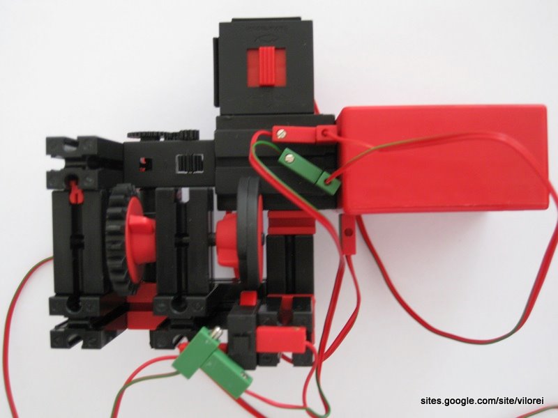
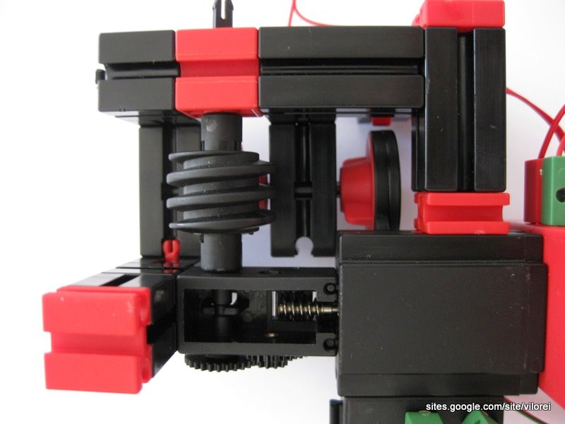
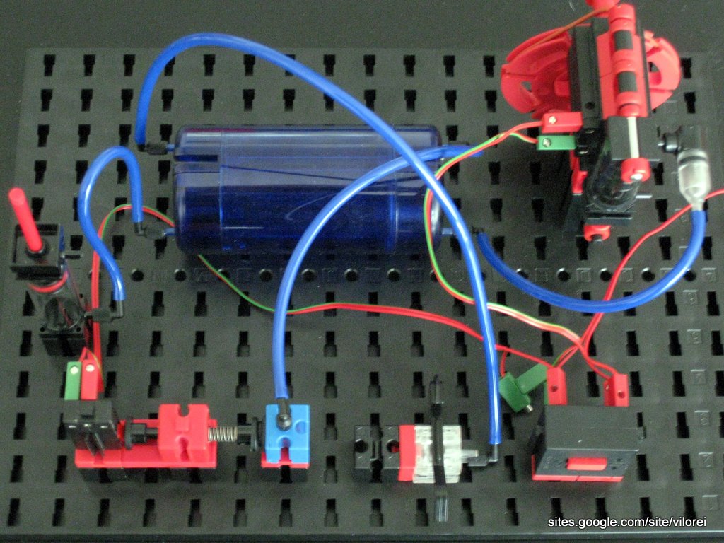
This first solution is fully autonomous. An adjustable shaft commands the production of compressed air.
Picture
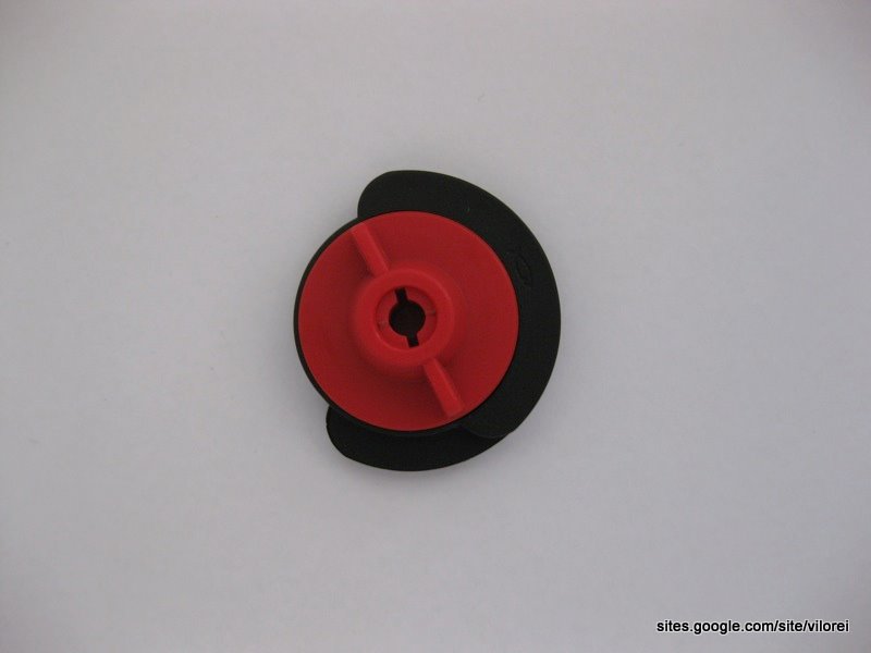
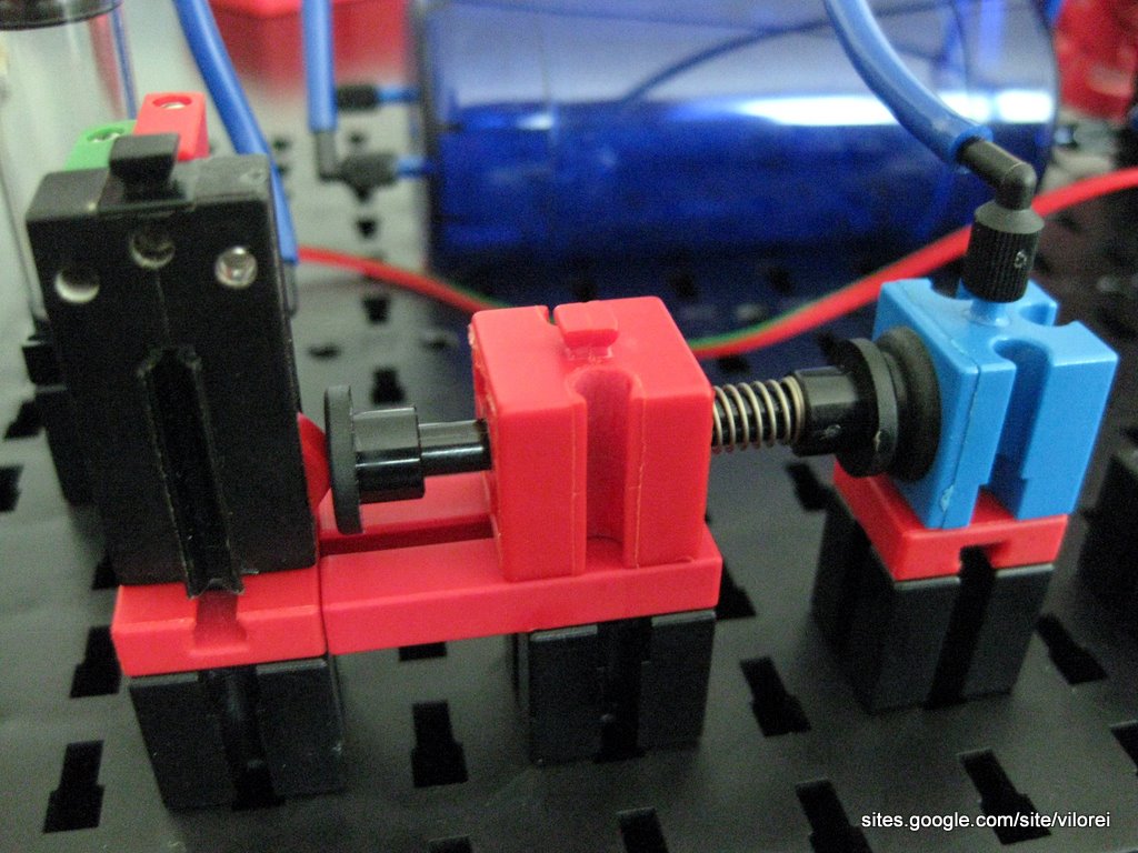
Detail of the shaft, easy to adjust.
Picture
Adjusting the shaft is needed to balance supply and demand. This solution works best for models with a regular use of compressed air.
Picture

2. Sensor Monitored Supply

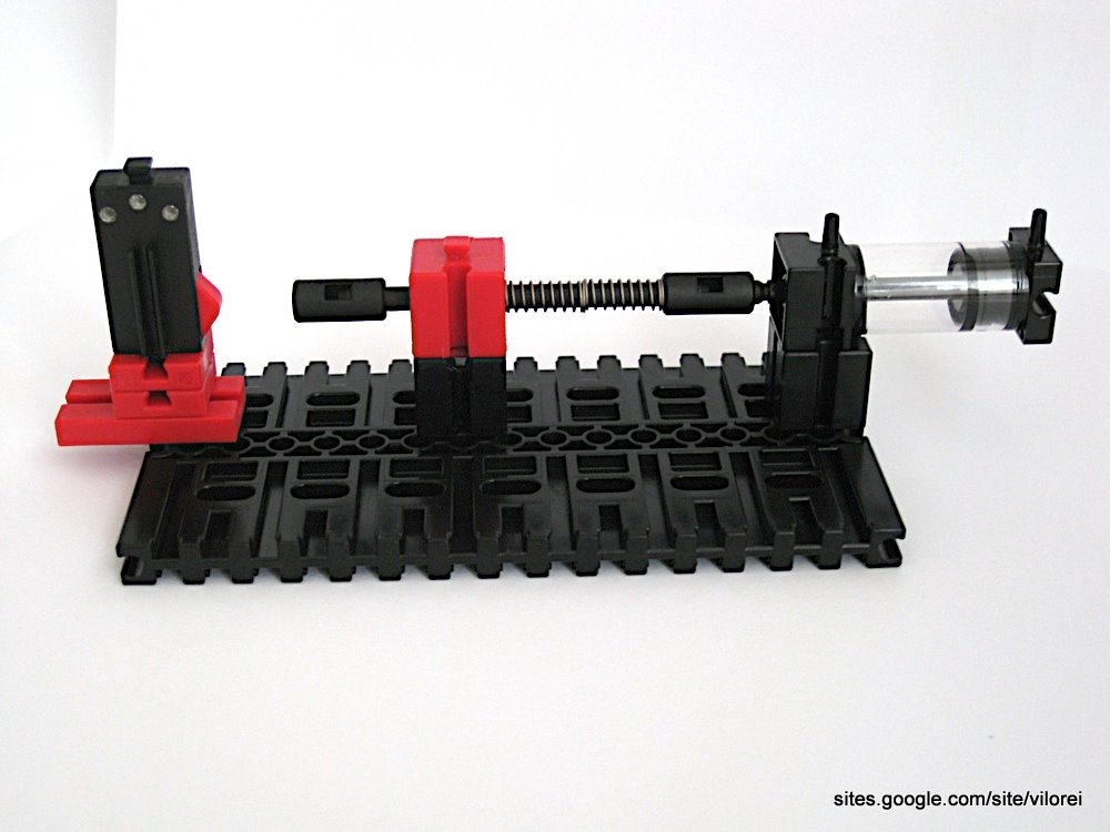
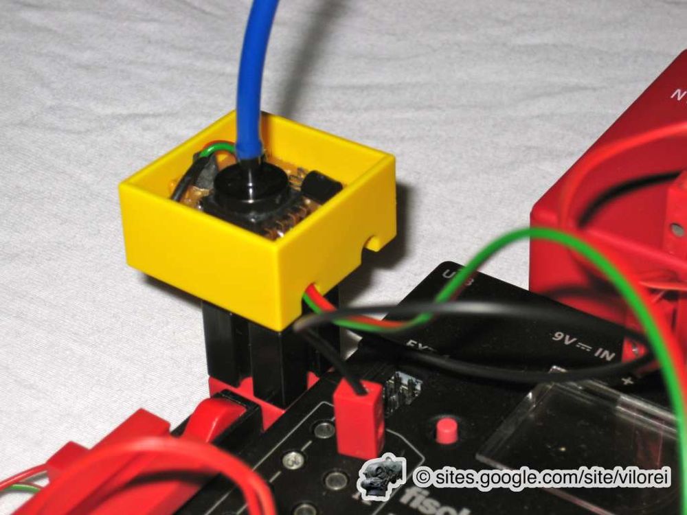
When use of compressed air is not regular, using a sensor could provide an efficient solution.
A short black cylinder is recommended because it has less friction.  

The sensor based solution fits continuous and non-critical usage. However, it's not recommended for vacuum-head, because low air pressure is detected as the very same time the vacuum head is running out of vacuum.

Since detection is simultaneous and fails to prevent the object from falling.

Below, the same system but with specific elements, as the blue valve reference 36075.
Picture
Picture
Picture
Picture
Picture
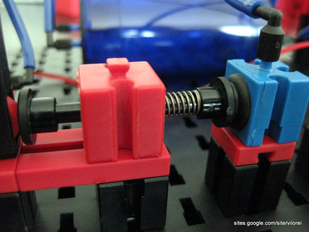
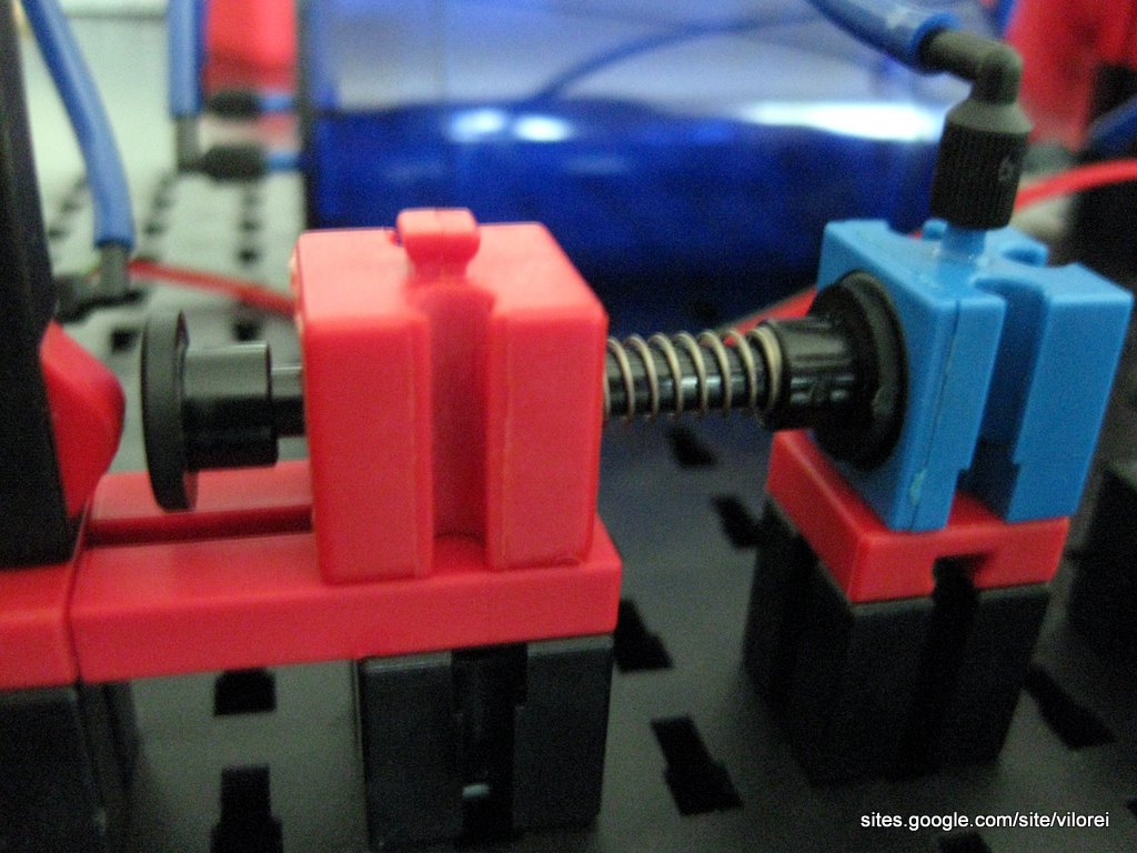
Left: low pressure ; Right: high pressure. 

3. Software Managed Compressor

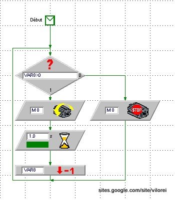
After having looked at mechanical solutions, let's explore what software could offer.

The following diagrams come from LLWin 3. 
There's no major difference with Robo Pro. 

First, a sub-routine manages the compressor in a smarter way.

The sub-routine checks VAR8, the messenger asking for compressed air.

VAR8 represents the number of seconds for compressed air generation. M8 is the compressor motor.
Picture
Picture
This sub-routine is launched when the model is started.

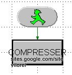
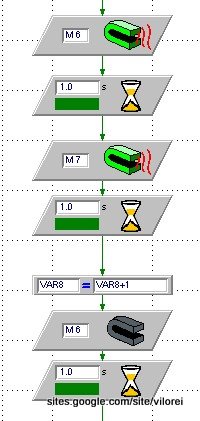
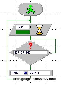
Let's see two examples:

Pressure has to be checked before and be ready for the use. 
  • On left, VAR8 is incremented before the compressed air usage. 
  • On right, E38 and E48 are variables activated when solenoids are switched on: VAR8 is incremented every 15 seconds to maintain constant pressure.
Picture
Picture

4. Digital Pressure Sensor

The management of the compressor motor by software could now be improved and integrate a precise measure of the pressure.

Such a measure is provided by a digital pressure sensor.
Picture

Conclusion

I've being playing with the three solutions: time, sensor based and software management of the compressor motor.The vacuum head (as in the PneuVac kit) demands constant high pressure. 

Problem is, when it is activated, the mechanical safety valve fails to prevent a small drop in pressure, and thus the cylinder carried out by the vaccum head falls. The same happens with the time based solution. Actually, the needs for vacuum head should be anticipated: only a software managed control could profide such a feature. 

This solution is used on the Magasin 9 model.

However, for models involving compressed air and not vacuum, the mechanical sensor provides a perfect answer. It also frees one motor from the time controlled solution and one output port from the software managed solution.
Powered by Create your own unique website with customizable templates.