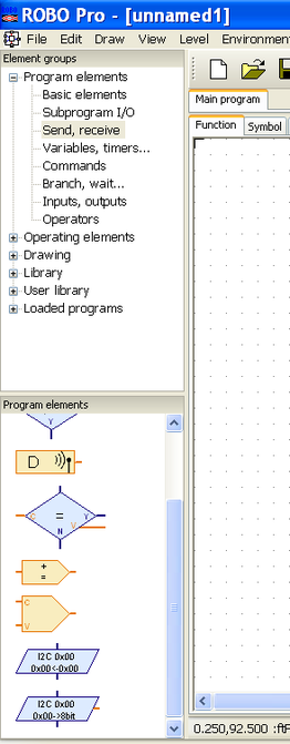
How to Manage an I²C Device?
|
Starting release 3.1.3, fischertechnik Robo Pro supports I²C devices and brings new dedicated functions.I²C devices are highly versatile and can be
The write and read functions required level 4 and are located under the send / receive group. Keep in mind:
Some I²C devices that work with the RoboTX controller may not work or work improperly with the Robotics TXT controller. |
|
Write Function

|
For more detailed informations, please refer to chapter 8.2.7 of the Robo Pro help. |
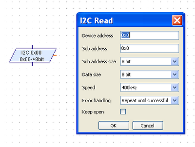
Read Function
|
For more detailed informations, please refer to chapter 8.2.7 of the Robo Pro help. |
Write or Read Mode Than Two Bytes
|
Let's take the example of the DS1307 real time clock. Both programs below are identical:
|
|
|
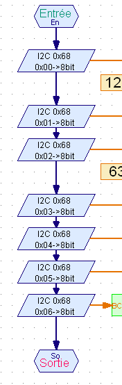
Reading one or two bytes
|
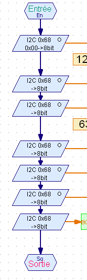
Reading more than two bytes in a sequence
|
|
To read more than 2 bytes, the keep open feature is used. In the case of the DS1307 real time clock, when a register is read, the internal address is incremented by one. So the next read command gets the next value. Each I²C device has its own registers and commands set, explained in the data-sheet. |
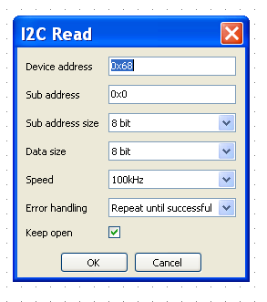
First command |
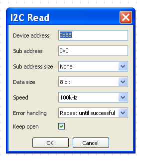
Following commands |
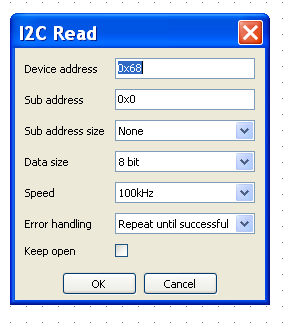
Last command |
|
|
|
|
The first command defines the device address and the sub-address. The sub-address may correspond to the address of a register of the device, or to a command for the device.
This first command opens a read sequence. |
In the following commands, there's no need to set the sub-address.
Here, another byte is read.
|
The only difference with the last command is that keep open is unchecked, and thus closes the read sequence.
|
|
Sounds complicated? Actually, it is. But there's a plug-and-play solution: the driver.
|
Operations Cycle
Using an I²C device always relies on the same operations cycle:
A driver packs all the functions for a full operation cycle.
- Initialisation: parameters to set the I²C device.
- Use: read or / and write operations.
- End: optionally, at the end.
A driver packs all the functions for a full operation cycle.
