Didacta Advance Pi-F5 interface board
|
After the fischertechnik-compatible interface board for the BBC micro:bit launched last year, Didacta Advance has announced three new interface boards.
They answer the wish I made after my initial review of the micro:bit IO F5 board: I hoped Didacta Advance would consider more powerful third-party boards, including single board computers like the Raspberry Pi or the BeagleBone. The new interface boards target the Arduino Uno and Arduino Mega micro-controller and the Raspberry Pi single board computer. fischertechnik mentions them in the Education Catalog 2020. I've ordered one Pi-F5 interface board for the Raspberry Pi and used it on a Raspberry Pi 3B and a Raspberry Pi Zero Wireless. |
|
Hardware
|
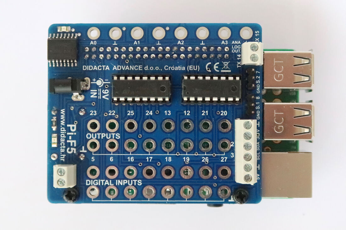
The board consists on two sections:
The fourteen inputs include height digital inputs for the switch (37783), the photo-transistor (36134) and the reed contact (36120), four analog inputs driven by the standard PCF8591 connected through I²C, and two servos. All the inputs are protected by the classic resistor and diode circuit. The eight outputs are driven by two standard L293x Quadruple Half-H Drivers mounted on sockets, easy to replace in case of over-current. Maximum current is 600 mA. So recommended actuators are the LED lamps (164134 and 164135) and the XS motor (137096). Finally, an I²C port brings expandability for I²C devices. The board features a 3.5 mm plug for the PLUS Power Set (505283) and also powers the controller board. Another reference features the 5.5 mm plug instead. |
|
Software
|
All the development solutions available for the Raspberry Pi can be used with:
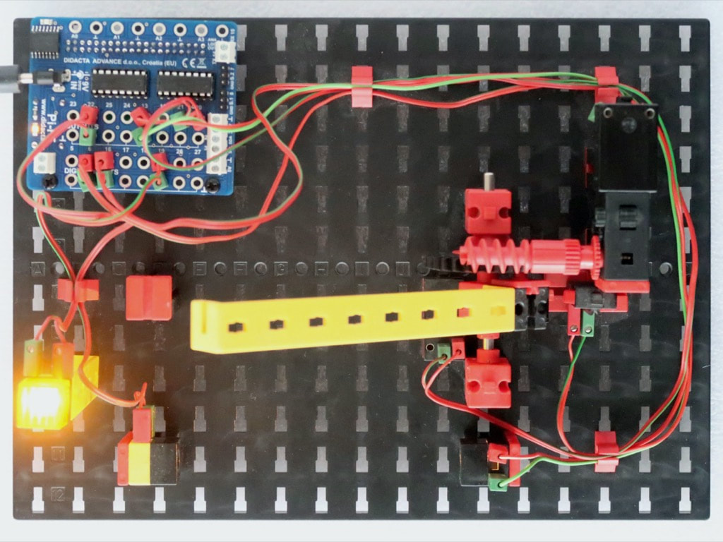
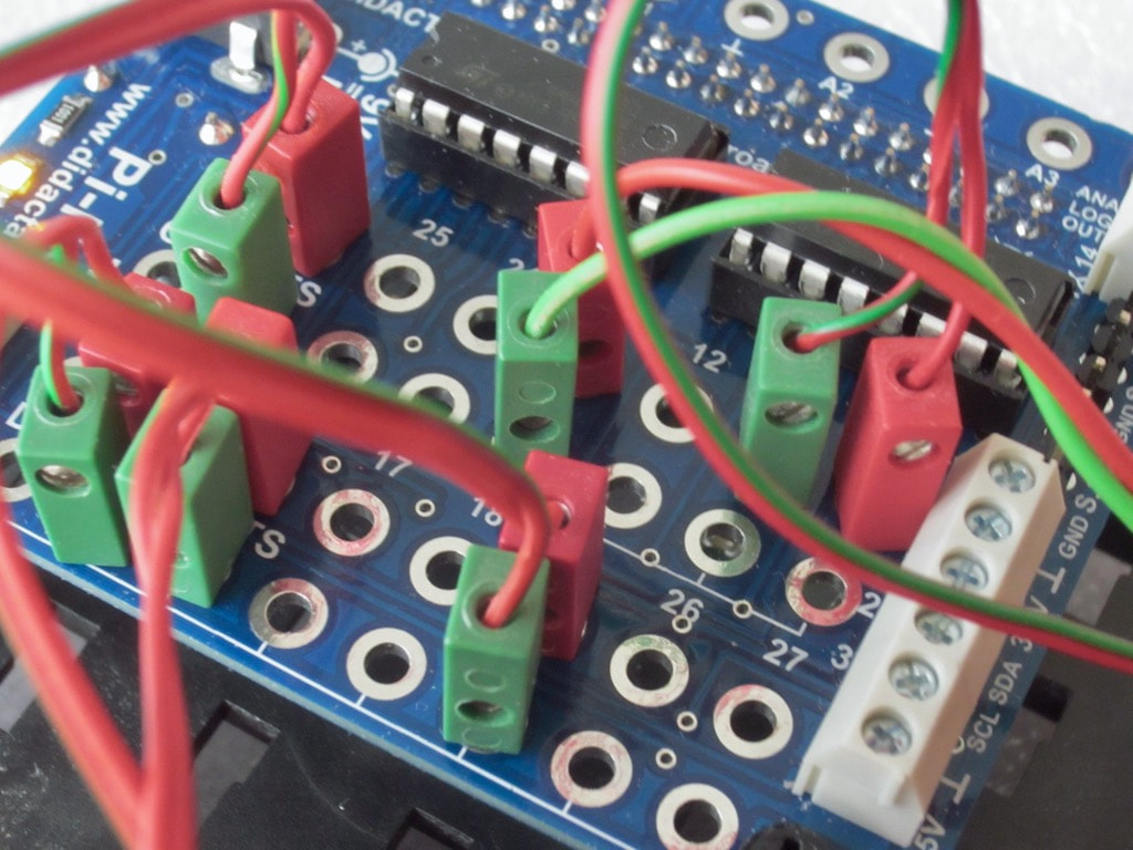
A pins map is provided with the board, but uses the numbering of the BCM2837 CPU GPIOs and not those of the 40-pin Raspberry Pi expansion connector. The Didacta Advance website offers many tutorials with examples on Python with the corresponding cabling (pictured right). The Raspberry website offers a nice introduction to Python with a list of IDEs and tutorials. An example for Python! |
|
Project One
|
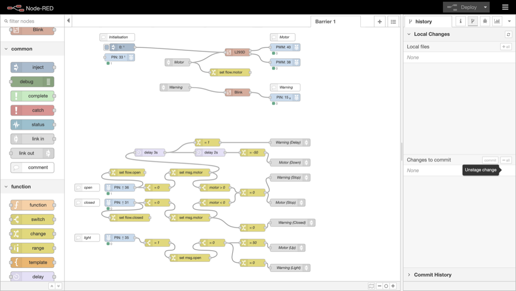
I started with the first project and used Node-RED.
I faced one issue, one difficulty and one limitation. The example ported to Node-RED |
|
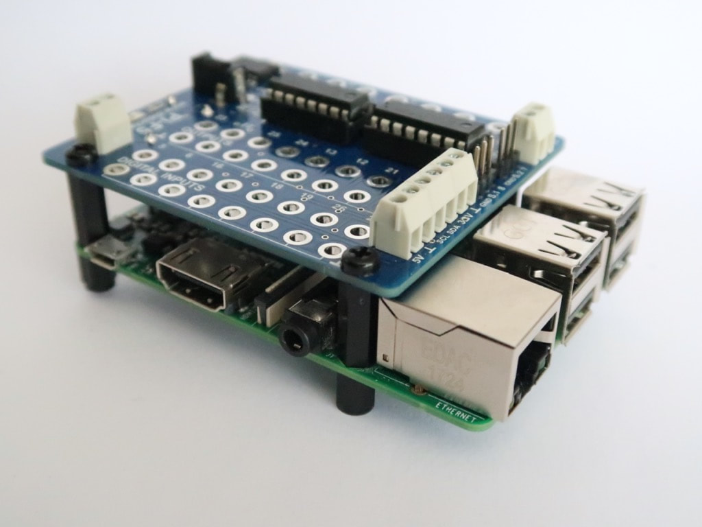
A first solution consists on using standoffs to increase the distance between the Raspberry Pi and the interface board. Another is to affix an electrical insulator to prevent any contact. Beware of the shorts! |
|
The Pi-F5 documentation stipulates 9 V 2.5 A as the minimal requirement, consistent with the fischertechnik Power Set (reference 505283) rated 9 V 2.5 A. Alas, this seems not to be enough to power both the Raspberry Pi 3B (recommended PSU 2.5 A) and the actuators (8 outputs rated at 600 mA and up to 1 A peak). I asked the support for help and was given two solutions. The MP2307 regulator can be adjusted to provide 5.1 V instead of the initial 5 V, to prevent voltage drops that may reset the Raspberry Pi. A better solution consists on using a more powerful power supply e.g. 9 V ~5 A. Using the Raspberry Pi Zero Wireless instead of the Raspberry Pi 3B also solves the problem, as the Raspberry Pi Zero Wireless requires half the power (recommended PSU 1.2 A). |
|
However, the photo-transistor output can be read through both analog and digital inputs. The analog to digital converter with 4 inputs and 1 output |
|
Using Node-RED and events
|
No surprise, I am a bing fan of Node-RED, which excels in IoT. Node-RED comes with all the tools to address the GPIO, even in PWM mode, and the I²C devices. However, Node-RED relies on events, while the initial algorithm was designed for sequential programming.
When defining a GPIO with Node-RED, the node displays a map of the GPIOs with the two numbering systems (pictured):
To read photo-transistor, I tried the two analog then digital options.
|
|
Playing with the automatic barrier model
|
I've reused the same model as last year, an automatic barrier model with
|
|
|
The events are triggered by the inputs the light barrier and the motor switches. They send messages which go through filters based on the current action, and finally define new commands.
Switching from sequential to event-based programming raised no major challenge, provided the initial analysis had been carried thoroughly with a special focus on priorities management |
|
Turning the projet into IIoT
|
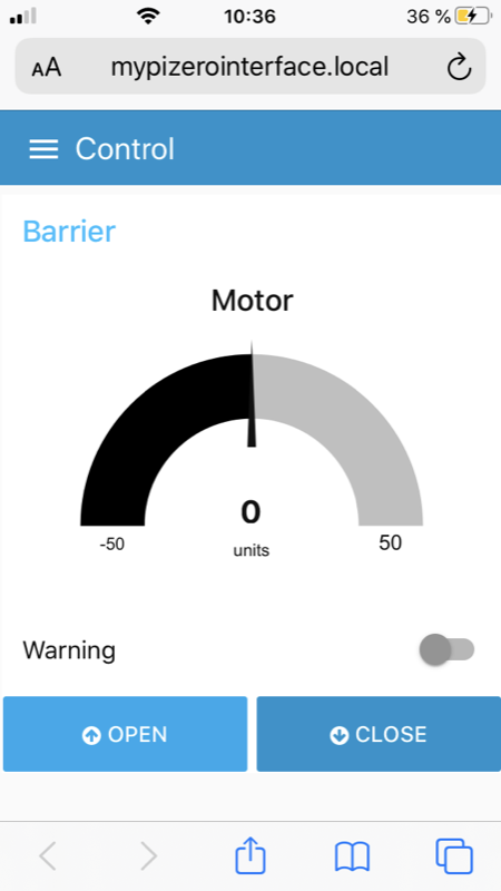
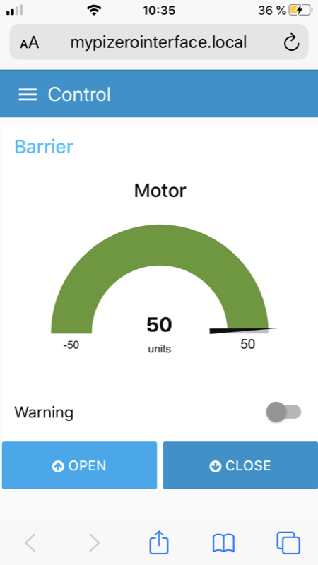
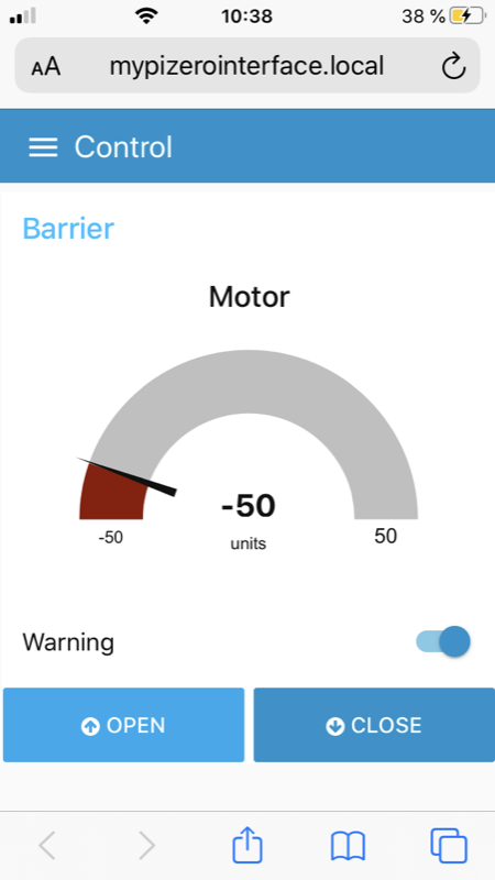
Once the flow was ready and tested, it was very easy to add IIoT features to the project, including remote command and control dashboard and MQTT messaging, both supported natively by Node-RED.
Then, the model can be controlled remotely, for example from a tablet! |
|
Finite-state machine to the rescue
|
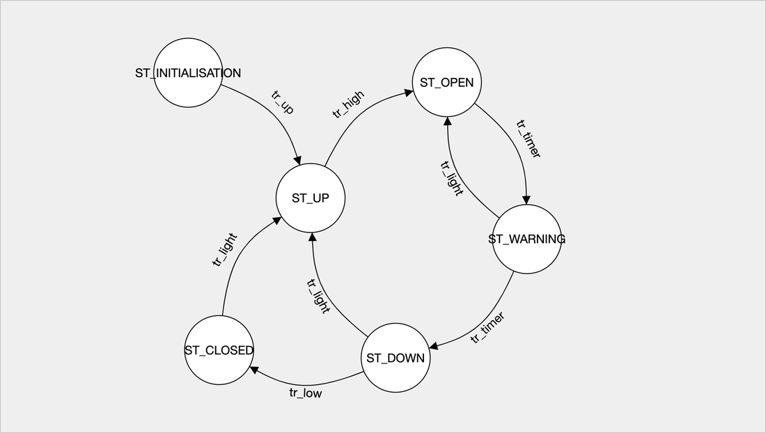
The initial flow wasn't very pretty nor easy to read, so I opted for implementing a solution based on a finite-state machine.
This method relies on an abstract model that lists a finite number of states —hence the name. Inputs can change the machine from one state to another: such changes are called transitions. A last element is the initial state the machine starts with. More details are available at Using Node-RED for IIoT. |
|
Conclusion
|
This series of new boards from Didacta Advance answers the wish I expressed last year, with more powerful third-party boards, including single board computers like the Raspberry Pi.
At less than 40€, the Raspberry Pi and the interface Pi-F5 board bundle is really affordable and delivers 12 inputs and 8 outputs, 2 servo connectors, an I²C port and a UART port, plus WiFi and Bluetooth. The Raspberry Pi brings all the tools with active support for IIoT projects. The interface board and the Raspberry Pi are not fixed to the fischertechnik model, contrary to the BBC micro:bit interface board. One idea would be to provide the files for a case to be 3D-printed. However, keep in mind the Raspberry Pi runs on Linux, and thus could not offer real-time deterministic monitoring or be considered as a PLC. A more advanced solution would rely on a dual-core configuration, with a CPU for dashboard and communication, and a dedicated MCU to drive the GPIOs. |
|
Pros
|
Cons
|
Wrap-Up
|
Links
|
|

Posted: 21 Feb 2020
Updated: 27 Feb 2020, 09 Mar 2020
