Digital Interface
|
The digital interface is very close to the previous analog interface except we are dealing with only two values, 0 or 1, and two channels. Thus we have four possibilities.
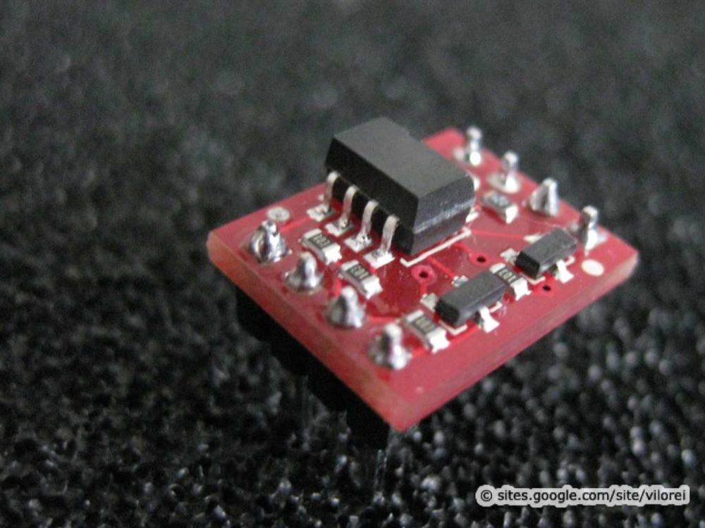
The circuit is based on an opto-isolator: the input powers a LED, which light is captured a photo-transistor that triggers the output (reference). |
|
On the Arduino Side
|
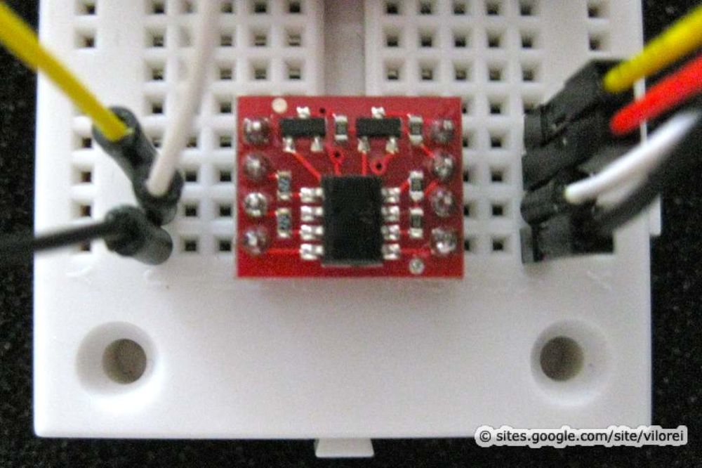
On the left, the connection to the Arduino.
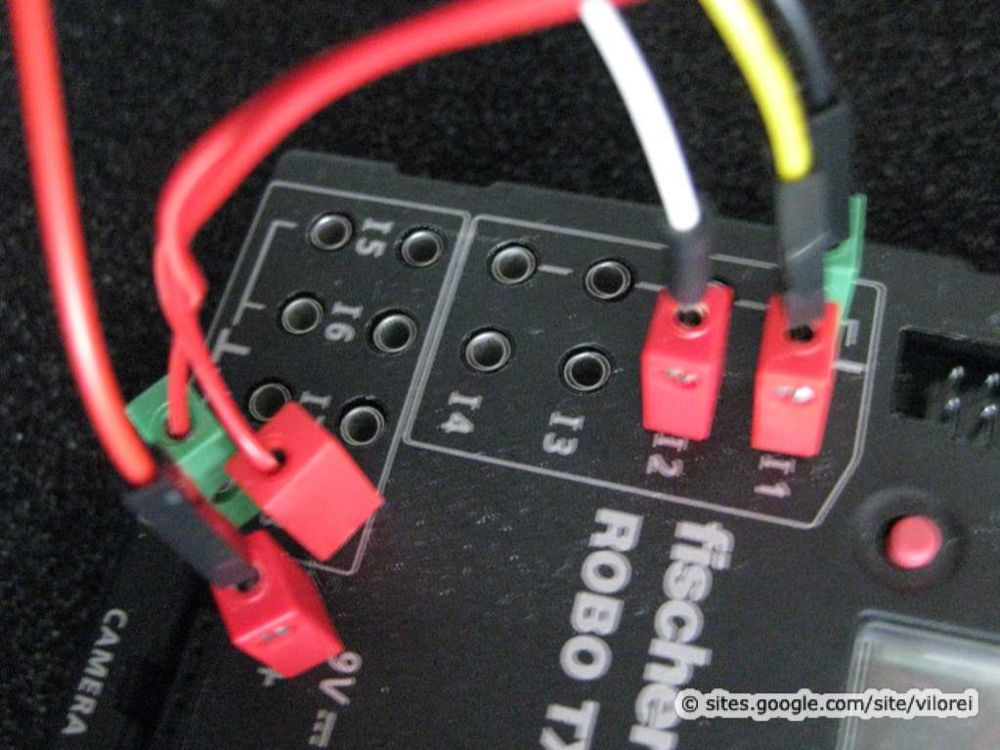
On the right, the connection to the Robo TX controller. Because there are two channels, 4 different values could be transferred:
|
|
|
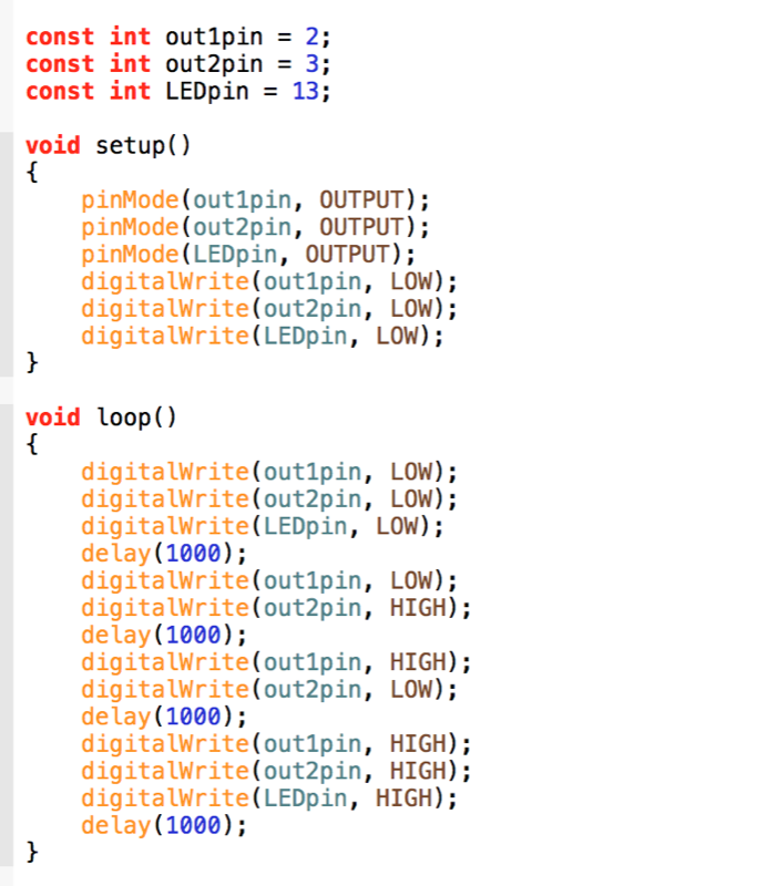
The Arduino program is fairly basic and explores the 4 values.
Note the LED on pin 13 as witness. |
|
On the Robo TX Side
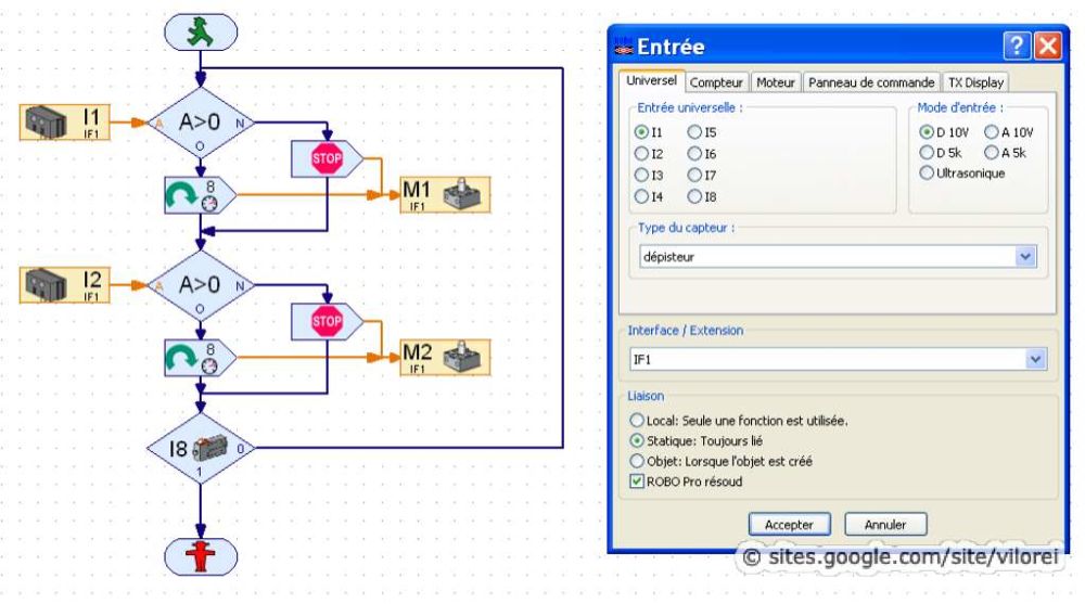
• WARNING AND DISCLAIMER The main program relies on two inputs, i1 and i2, both digital 10V.
The main program reads the two digital inputs i1 and i2 and lights on lamps m1 and m2 accordingly, offering the 4 possibilities: |
|
Possible Applications
|
The Arduino can read advanced sensors, process the data and send the result as a digital value to the TX controller.
|
Previous |
Next |
