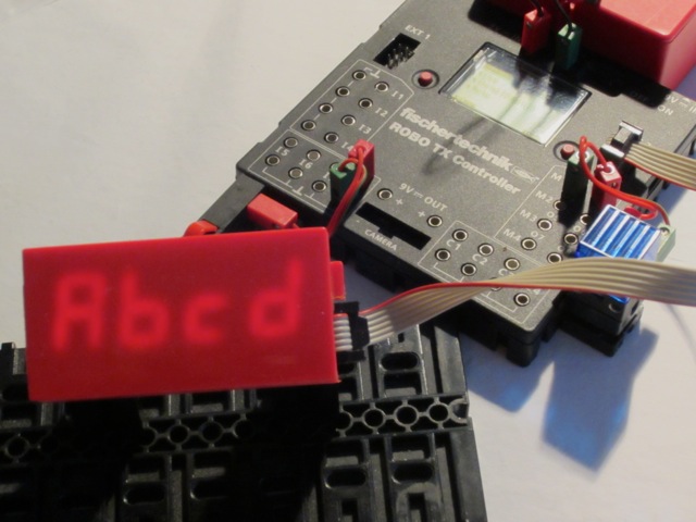
Rei Vilo's fischertechnik Corner
  • About
  • Blog
  • Reviews
    • How to Start?
    • Controllers >
      • Robotics TXT
      • TXT 4.0 Controller
      • Bluetooth Smart Beginner Set
      • Interface Boards for fischertechnik Models
      • Didacta Advance Pi-F5 interface board
    • Sets >
      • Technical Revolutions Set
      • Pneumatic Power Set
      • Automation Robots Set
      • Electro-Pneumatic Set
      • Starter Set for micro:bit
      • Bluetooth Smart Beginner Set
      • Robotics TXT Smart Home Set
    • Exploring the Lego World >
      • Purchasing
      • Unboxing
      • Installing
      • Building
      • Programming
      • Connecting
      • Playing
      • Expanding
      • Concluding
  • Models
    • Back to the 70's
    • Micro Models
    • New Magasin >
      • Magasin releases 1, 2 and 3
      • Long X-Axis
      • Moving Desk And Y-Axis
      • Compressed Air And Vacuum For Z-Axis
      • Pictures
      • Specifications
    • Power Saving White LED
    • Flipper with I²C LCD Panel
    • Celebrating 50 Years!
    • ft Convention 2013
    • ft Convention 2014
  • Sensors
    • Interfacing an Arduino to a Robo TX Controller >
      • Analog Interface
      • Digital Interface
      • I²C Interface
    • Standard Sensors >
      • Playing With Accelerometers
      • Proximity Sensor
      • Pressure Sensor
    • Advanced Sensors >
      • Industrial Colour Reader
      • Stepper Motor Controller
      • DC-Motor with Quadrature Encoder Controller
    • smartDevices >
      • smartColours
      • smartRFID
      • smartLED
      • smartHub
      • smartControls
      • smartMeter
      • smartCamera
      • smartNewCamera
      • smartWiFi
      • smartBLE
      • smartNode
      • smartIMU
  • RoboPro
    • Value Operations >
      • Min and Max Functions
      • Signal Management With Median
      • Modulo Function
      • Map Function
    • Standard Modules >
      • Software Managed Compressor
      • Self-Calibrated Colour-Reader
      • Standard Conveyor Belt Routine
      • Management Panel
      • Encoder-Motor Position Management
    • Variable Types >
      • CSV List Management
      • Queue Function
    • Program Structures >
      • Parallel Processing
      • Multi-Tasking End Management Procedure
    • Tutorials >
      • Setting Bluetooth LAN with Multiple TX-Cs
      • Dealing with Very Large Models >
        • Getting a General View
        • Defining User's Functions
        • Elaborating the Modelisation
        • Defining the Processes
        • Setting the Messages
        • Going Further
        • References
      • Program Error 2 Message
  • I²C
    • How to Connect an I²C Device to the Robo TX?
    • How to Connect an I²C Device to the Robotics TXT?
    • How to Manage an I²C Device?
    • How to Use an I²C Driver?
    • List of I²C Drivers for Sensors >
      • I²C Real Time Clock DS1307
      • I²C LCD screen 4 lines of 20 characters LCD03
      • I²C Triple Axis Accelerometer ADXL345
      • I²C Red-Green-Blue LED BlinkM
      • I²C Two Axis Compass HMC6352
      • I²C Triple Axis Magnetometer HMC5843
      • I²C True Colour Sensor ADJD-S371
      • I²C Stepper Controller AMIS-30624
    • List of I²C Drivers for smartDevices >
      • I²C True Colours Smart Sensor smartColours
      • I²C RFID Smart Sensor smartRFID
      • I²C 4-Digit 7-Segment LED Display smartLED
      • I²C Screen With Touch and SD-Card smartControls
      • I²C Smart Sensor smartCamera
      • I²C Smart Sensor smartNewCamera
      • I²C Remote WiFi Interface smartWiFi​
      • I²C Remote Bluetooth Interface smartBLE​
      • I²C Remote Interface smartNode​
      • I²C New LCD Screen 4 x 20 characters smartLCD
      • I²C Inertial Measurement Unit smartIMU

smartLED

The smartLED is a 4-digit 7-segment display encased in a 9V red battery box (references 32263 and 32958). 

It is connected to the TX controller through I²C.

The 9V red battery box makes it perfect to be included in a fischertechnik model.
Picture

Commands

The command begin initialises the display and the command clear switches all segments off.

The value sent to the display can be decimal —range 0000~9999— or hexadecimal —range 0x0000~0xffff.

A decimal point can be defined and leading zeroes omitted. 00.12 is displayed as  0.12, with the first zero omitted.

A specific command defines the segments to light on for a given digit, based on the binary coding of the segments:
  • bit 0 = 2^0 = 1 = 0x01 for segment a
  • bit 1 = 2^1 = 2 = 0x02 for segment b
  • bit 2 = 2^2 = 4 = 0x04 for segment c
  • bit 3 = 2^3 = 8 = 0x08 for segment d
  • bit 4 = 2^4 = 16 = 0x10 for segment e
  • bit 5 = 2^5 = 32 = 0x20 for segment f
  • bit 6 = 2^6 = 64 = 0x40 for segment g
  • bit 7 = 2^7 = 128 = 0x80 for the decimal point or for the column between hours or minutes, depending on the display

For example, 
  • Displaying a capital A requires lighting the segments a, b, c, e, f and g. Adding a + b + c + e + f + g = 1 + 2 + 4 + 16 + 32 + 64 gives 119 or 0x77.
  • Displaying the minus sign only requires the g segment, thus 64 = 0x40.

The I²C 4-Digit 7-Segment LED DIsplay smartLED page provides more details about the commands and the RoboPro visual interface.
Picture
Picture

Finalised and Working Sensor

Thanks to the previously developed sensors, only one proof of concept was needed before the first batch.
Picture
Powered by Create your own unique website with customizable templates.