Rei Vilo's fischertechnik Corner
  • About
  • Blog
  • Reviews
    • How to Start?
    • Controllers >
      • Robotics TXT
      • TXT 4.0 Controller
      • Bluetooth Smart Beginner Set
      • Interface Boards for fischertechnik Models
      • Didacta Advance Pi-F5 interface board
    • Sets >
      • Technical Revolutions Set
      • Pneumatic Power Set
      • Automation Robots Set
      • Electro-Pneumatic Set
      • Starter Set for micro:bit
      • Bluetooth Smart Beginner Set
      • Robotics TXT Smart Home Set
    • Exploring the Lego World >
      • Purchasing
      • Unboxing
      • Installing
      • Building
      • Programming
      • Connecting
      • Playing
      • Expanding
      • Concluding
  • Models
    • Back to the 70's
    • Micro Models
    • New Magasin >
      • Magasin releases 1, 2 and 3
      • Long X-Axis
      • Moving Desk And Y-Axis
      • Compressed Air And Vacuum For Z-Axis
      • Pictures
      • Specifications
    • Power Saving White LED
    • Flipper with I²C LCD Panel
    • Celebrating 50 Years!
    • ft Convention 2013
    • ft Convention 2014
  • Sensors
    • Interfacing an Arduino to a Robo TX Controller >
      • Analog Interface
      • Digital Interface
      • I²C Interface
    • Standard Sensors >
      • Playing With Accelerometers
      • Proximity Sensor
      • Pressure Sensor
    • Advanced Sensors >
      • Industrial Colour Reader
      • Stepper Motor Controller
      • DC-Motor with Quadrature Encoder Controller
    • smartDevices >
      • smartColours
      • smartRFID
      • smartLED
      • smartHub
      • smartControls
      • smartMeter
      • smartCamera
      • smartNewCamera
      • smartWiFi
      • smartBLE
      • smartNode
      • smartIMU
  • RoboPro
    • Value Operations >
      • Min and Max Functions
      • Signal Management With Median
      • Modulo Function
      • Map Function
    • Standard Modules >
      • Software Managed Compressor
      • Self-Calibrated Colour-Reader
      • Standard Conveyor Belt Routine
      • Management Panel
      • Encoder-Motor Position Management
    • Variable Types >
      • CSV List Management
      • Queue Function
    • Program Structures >
      • Parallel Processing
      • Multi-Tasking End Management Procedure
    • Tutorials >
      • Setting Bluetooth LAN with Multiple TX-Cs
      • Dealing with Very Large Models >
        • Getting a General View
        • Defining User's Functions
        • Elaborating the Modelisation
        • Defining the Processes
        • Setting the Messages
        • Going Further
        • References
      • Program Error 2 Message
  • I²C
    • How to Connect an I²C Device to the Robo TX?
    • How to Connect an I²C Device to the Robotics TXT?
    • How to Manage an I²C Device?
    • How to Use an I²C Driver?
    • List of I²C Drivers for Sensors >
      • I²C Real Time Clock DS1307
      • I²C LCD screen 4 lines of 20 characters LCD03
      • I²C Triple Axis Accelerometer ADXL345
      • I²C Red-Green-Blue LED BlinkM
      • I²C Two Axis Compass HMC6352
      • I²C Triple Axis Magnetometer HMC5843
      • I²C True Colour Sensor ADJD-S371
      • I²C Stepper Controller AMIS-30624
    • List of I²C Drivers for smartDevices >
      • I²C True Colours Smart Sensor smartColours
      • I²C RFID Smart Sensor smartRFID
      • I²C 4-Digit 7-Segment LED Display smartLED
      • I²C Screen With Touch and SD-Card smartControls
      • I²C Smart Sensor smartCamera
      • I²C Smart Sensor smartNewCamera
      • I²C Remote WiFi Interface smartWiFi​
      • I²C Remote Bluetooth Interface smartBLE​
      • I²C Remote Interface smartNode​
      • I²C New LCD Screen 4 x 20 characters smartLCD
      • I²C Inertial Measurement Unit smartIMU

How to Connect an I²C Device to the Robotics TXT?

fischertechnik Robotics TXT controller has one extension port, EXT. This port operates at 3.3 V level.

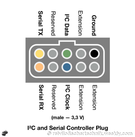
The extension port EXT supports I²C connection, with 3 active wires: 
  • ​Ground, 
  • I²C Clock, and
  • I²C Data.
Contrary to what has been posted in the ft:c forum, video and even issue 2015-4 of ft-pedia, pin 9 of the extension port does not provide +3.3V power supply. 

​
Do not use pin 9 as 3.3 V source.
Picture
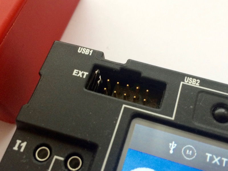
The EXT connector for I²C on the Robotics TXT controller
Picture

I²C only defines a bus protocol, nothing more. 
  • Each I²C device is different: it may require 5 V or 3,3 V or even 1,8 V, runs at 100 or 400 kHz, and brings its own specific command set.
  • Before using any I²C device, read the specification sheet and the application notes very carefully! 
Otherwise, the I²C device and even the Robotics TXT controller may be damaged irremediably.
​
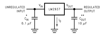
How to power the sensor with 3.3 V?

There's no special difficulty in assembling a separate 3.3 V power line with a LM2937-3.3 or LM1117-3.3, or similar based on the estimated power consumption of the devices.

The unregulated input is connected to the +9V output of the Robotics TXT, and so does Ground to Ground.

Picture

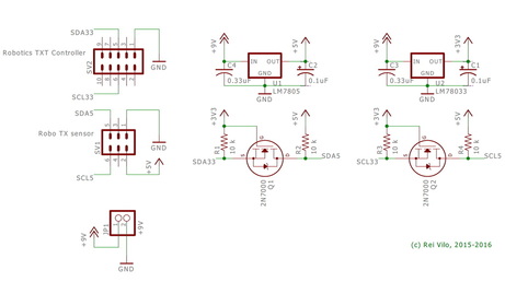
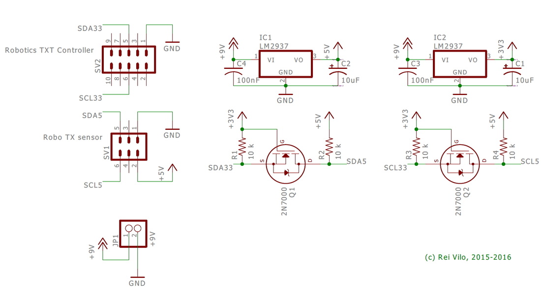
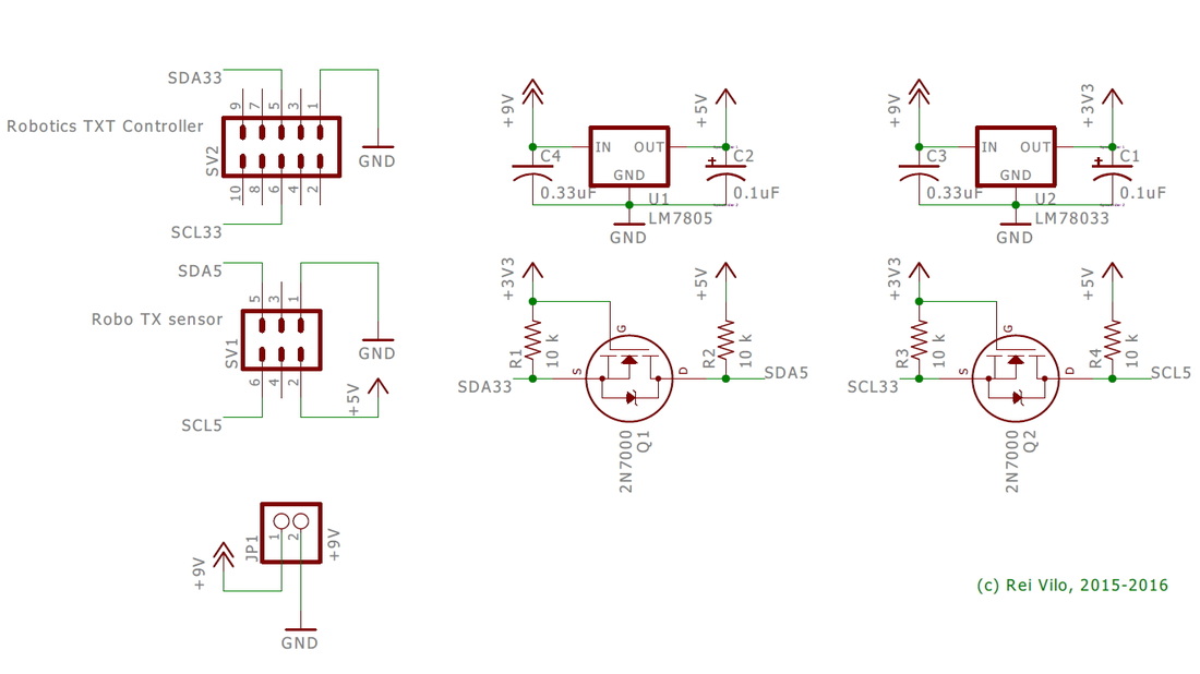
Connecting 5 V I²C Devices to Robotics TXT Controller

Some of the I²C devices I've developed libraries for, like the AMIS-30624 stepper controller or the 4 lines x 20 characters LCD display, run at 5 V.

​The circuit requires dual regulators for 3.3 V and 5 V power lines, and MOSFETs or PCA9306 to step-up I²C signals from 3.3 V to 5 V. Please refer to the different I²C Logic Level Converter options and the official Level shifting techniques in I2C-bus design application note from NXP. 

​Some voltage regulators require a minimum power usage to ensure good stability. In such a case, just place a LED with a limiting resistor on the 3.3 V power rail. 

The two circuits on the right combine the solutions mentioned above.
​
• Caution
The schematics supplied are for illustrative purpose only.
​Please read the specification sheets carefully and check the voltage and current requirements. 
​Otherwise, the I²C device and even the controller (RoboTX or 
Robotics TXT) may be damaged irremediably.
Picture

Compatibility Issues

The I²C implementation in RoboPRO 4.2.4 for the Robotics TXT controller suffers from three limitations:
  • Although the Robotics TXT controller supports I²C clock stretching, one slave I²C device can no longer drive the clock line low in a MultiMaster configuration, as it was possible with the previous generation RoboTX controller.
  • Similarly, RoboPro 4.2.4 doesn't configure the I²C mode properly on the Robotics TXT controller. Even if standard mode (100 kHz) is selected, the controller runs in fast mode (400 kHz). Some I²C devices may not work if they don't support fast mode (400 kHz).
  • Despite the two cores (MPU and MCU), the Robotics TXT controller doesn't support fast mode plus (1 MHz).

Luckily, the RoboTX controller fully supports I²C fast mode (400 kHz).
​
I do not recommend the logic level converter for I²C described in issue 2016-4 of ft-pedia, as it doesn't match with the Level shifting techniques in I2C-bus design application note from NXP.
The circuit proposed on issue 2016-4 of ft-pedia doesn't match with the Level shifting techniques in I2C-bus design application note from NXP.

Previous

  • How to connect an I²C Device to the Robo TX?

Next

  • How to Manage an I²C Device?
Powered by Create your own unique website with customizable templates.