Automation Robots Set — High Bay Storage Rack Fixes
|
The high bay storage rack from the Robo TX Automation Robots set is an amazing piece of engineering.
However, it requires a precision of less than 1 mm, close to fischertechnik system limits. Some axis are too tight, some parts require manual adjustment. Here are the modifications I brought to the initial design in order to improve the reliability of the model. Please refer to the manual for the parts list corresponding to the mentioned steps. |
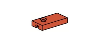
Step 4
|
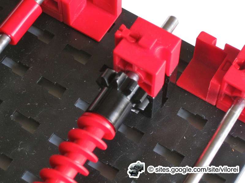
The X-axis is too tight.
|
|


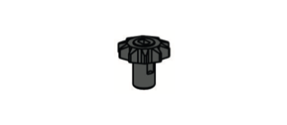
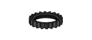
35031 + 31021 + 31058
|
|


Step 8
|
|
|
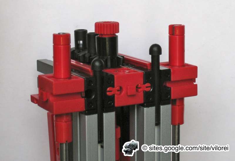
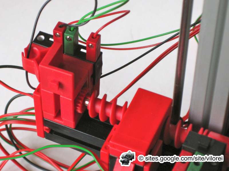
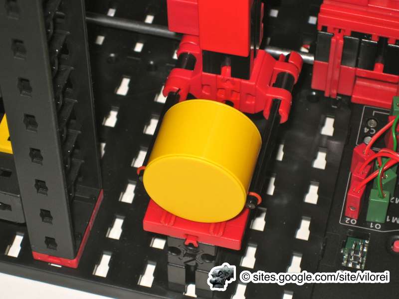
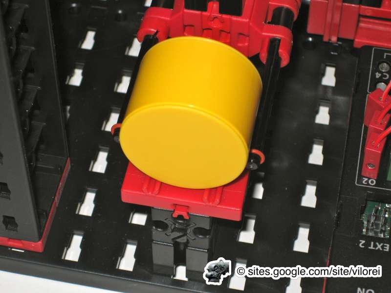
Step 20
|
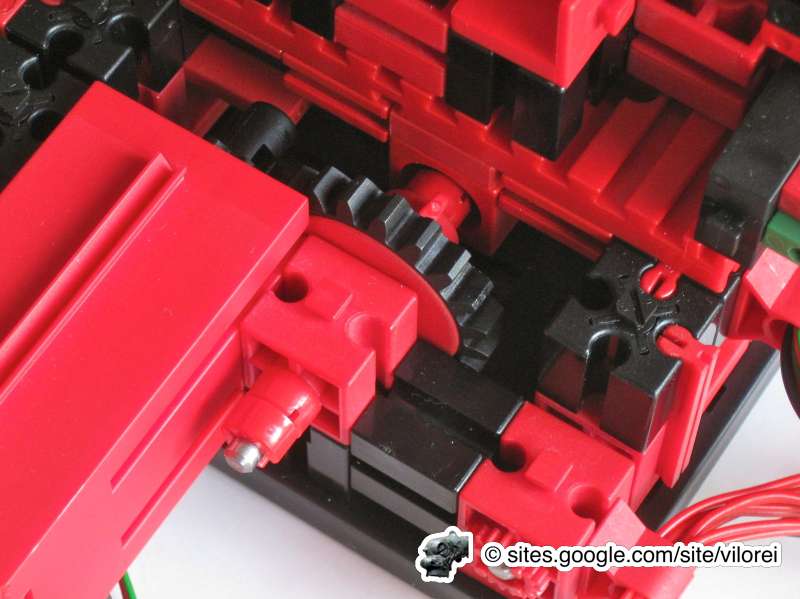
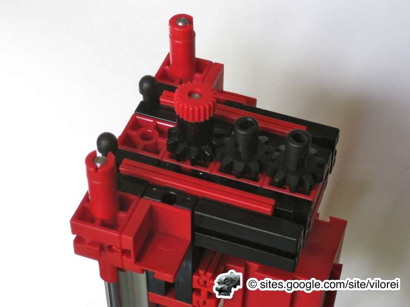
The Y-axis motor collides with the 32870.
|
|

|
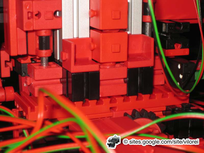
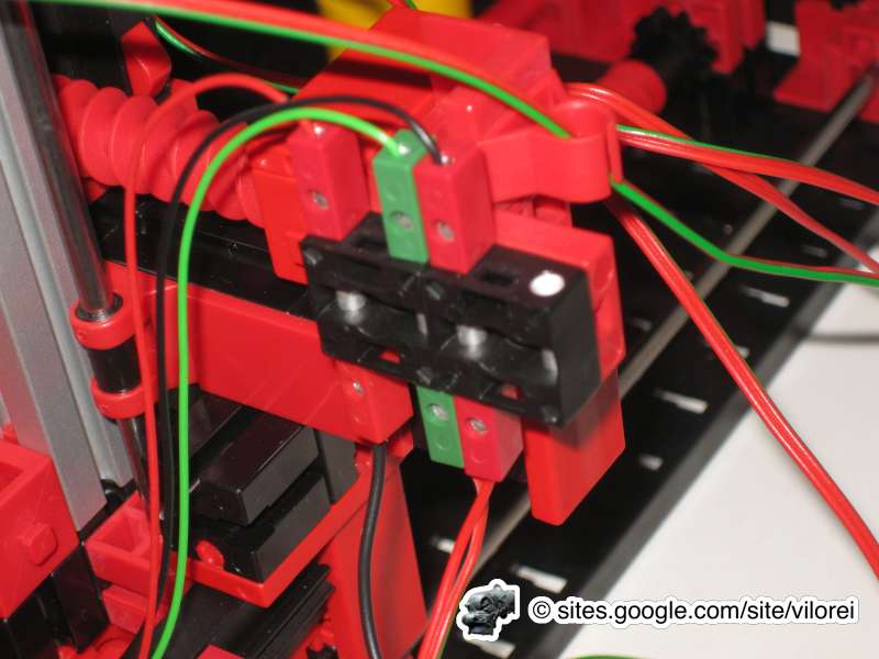
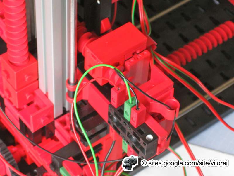
Cables mess with the linear translator.
|
|
|
|
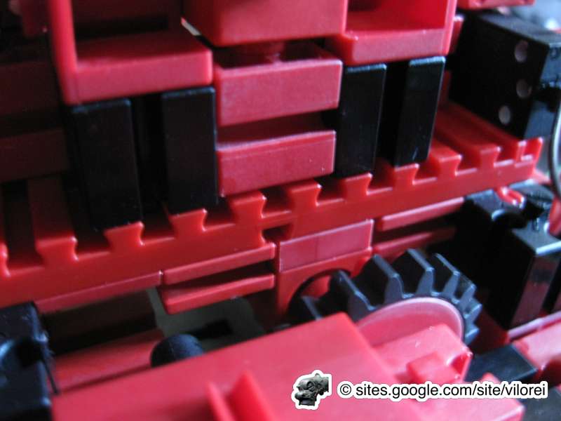
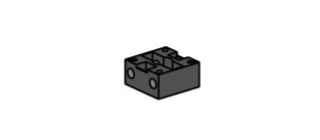
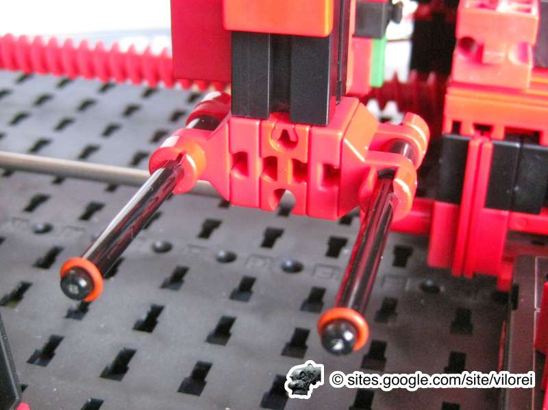
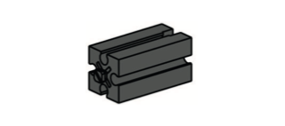
Step 22
|
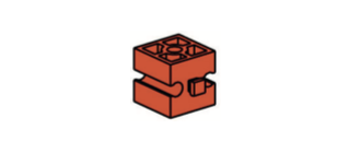
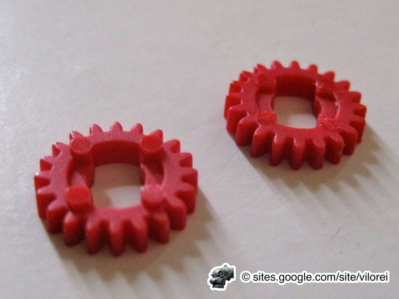
The BOM doesn't supply enough 31061. 31330 is recommended for better stability.
|
|

|
The Z-axis is too tight.
|
|

|
|

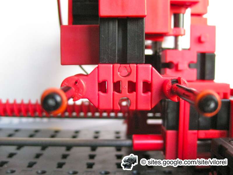
Step 23
|
The position of the head needs to be manually adjusted to be just in front of the input/output area and the storage areas.
|
|
|
|


|
|
|
