Rei Vilo's fischertechnik Corner
  • About
  • Blog
  • Reviews
    • How to Start?
    • Controllers >
      • Robotics TXT
      • TXT 4.0 Controller
      • Bluetooth Smart Beginner Set
      • Interface Boards for fischertechnik Models
      • Didacta Advance Pi-F5 interface board
    • Sets >
      • Technical Revolutions Set
      • Pneumatic Power Set
      • Automation Robots Set
      • Electro-Pneumatic Set
      • Starter Set for micro:bit
      • Bluetooth Smart Beginner Set
      • Robotics TXT Smart Home Set
    • Exploring the Lego World >
      • Purchasing
      • Unboxing
      • Installing
      • Building
      • Programming
      • Connecting
      • Playing
      • Expanding
      • Concluding
  • Models
    • Back to the 70's
    • Micro Models
    • New Magasin >
      • Magasin releases 1, 2 and 3
      • Long X-Axis
      • Moving Desk And Y-Axis
      • Compressed Air And Vacuum For Z-Axis
      • Pictures
      • Specifications
    • Power Saving White LED
    • Flipper with I²C LCD Panel
    • Celebrating 50 Years!
    • ft Convention 2013
    • ft Convention 2014
  • Sensors
    • Interfacing an Arduino to a Robo TX Controller >
      • Analog Interface
      • Digital Interface
      • I²C Interface
    • Standard Sensors >
      • Playing With Accelerometers
      • Proximity Sensor
      • Pressure Sensor
    • Advanced Sensors >
      • Industrial Colour Reader
      • Stepper Motor Controller
      • DC-Motor with Quadrature Encoder Controller
    • smartDevices >
      • smartColours
      • smartRFID
      • smartLED
      • smartHub
      • smartControls
      • smartMeter
      • smartCamera
      • smartNewCamera
      • smartWiFi
      • smartBLE
      • smartNode
      • smartIMU
  • RoboPro
    • Value Operations >
      • Min and Max Functions
      • Signal Management With Median
      • Modulo Function
      • Map Function
    • Standard Modules >
      • Software Managed Compressor
      • Self-Calibrated Colour-Reader
      • Standard Conveyor Belt Routine
      • Management Panel
      • Encoder-Motor Position Management
    • Variable Types >
      • CSV List Management
      • Queue Function
    • Program Structures >
      • Parallel Processing
      • Multi-Tasking End Management Procedure
    • Tutorials >
      • Setting Bluetooth LAN with Multiple TX-Cs
      • Dealing with Very Large Models >
        • Getting a General View
        • Defining User's Functions
        • Elaborating the Modelisation
        • Defining the Processes
        • Setting the Messages
        • Going Further
        • References
      • Program Error 2 Message
  • I²C
    • How to Connect an I²C Device to the Robo TX?
    • How to Connect an I²C Device to the Robotics TXT?
    • How to Manage an I²C Device?
    • How to Use an I²C Driver?
    • List of I²C Drivers for Sensors >
      • I²C Real Time Clock DS1307
      • I²C LCD screen 4 lines of 20 characters LCD03
      • I²C Triple Axis Accelerometer ADXL345
      • I²C Red-Green-Blue LED BlinkM
      • I²C Two Axis Compass HMC6352
      • I²C Triple Axis Magnetometer HMC5843
      • I²C True Colour Sensor ADJD-S371
      • I²C Stepper Controller AMIS-30624
    • List of I²C Drivers for smartDevices >
      • I²C True Colours Smart Sensor smartColours
      • I²C RFID Smart Sensor smartRFID
      • I²C 4-Digit 7-Segment LED Display smartLED
      • I²C Screen With Touch and SD-Card smartControls
      • I²C Smart Sensor smartCamera
      • I²C Smart Sensor smartNewCamera
      • I²C Remote WiFi Interface smartWiFi​
      • I²C Remote Bluetooth Interface smartBLE​
      • I²C Remote Interface smartNode​
      • I²C New LCD Screen 4 x 20 characters smartLCD
      • I²C Inertial Measurement Unit smartIMU

Another Sensor

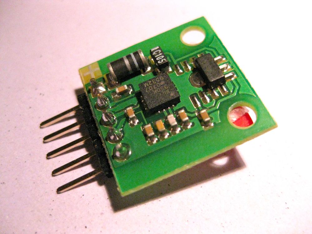
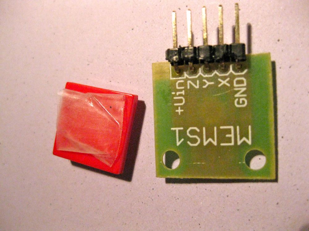
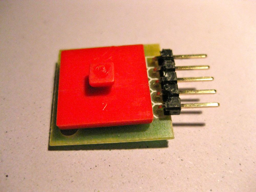
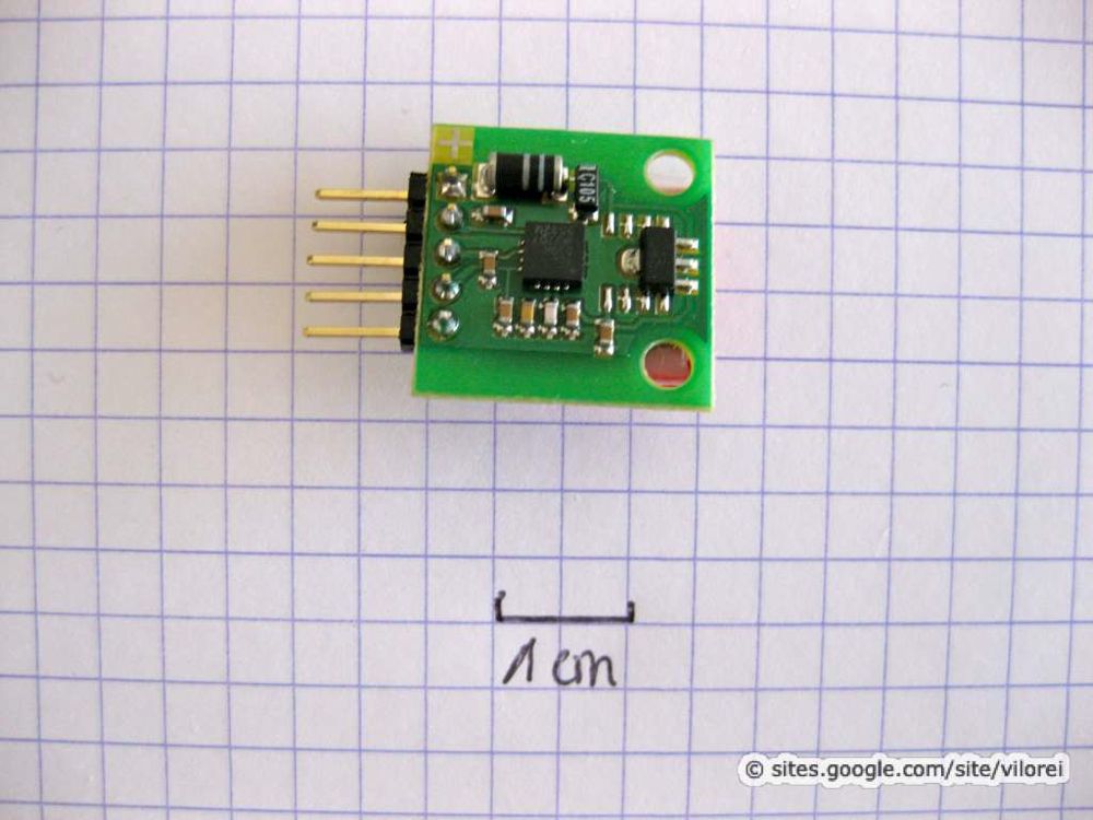
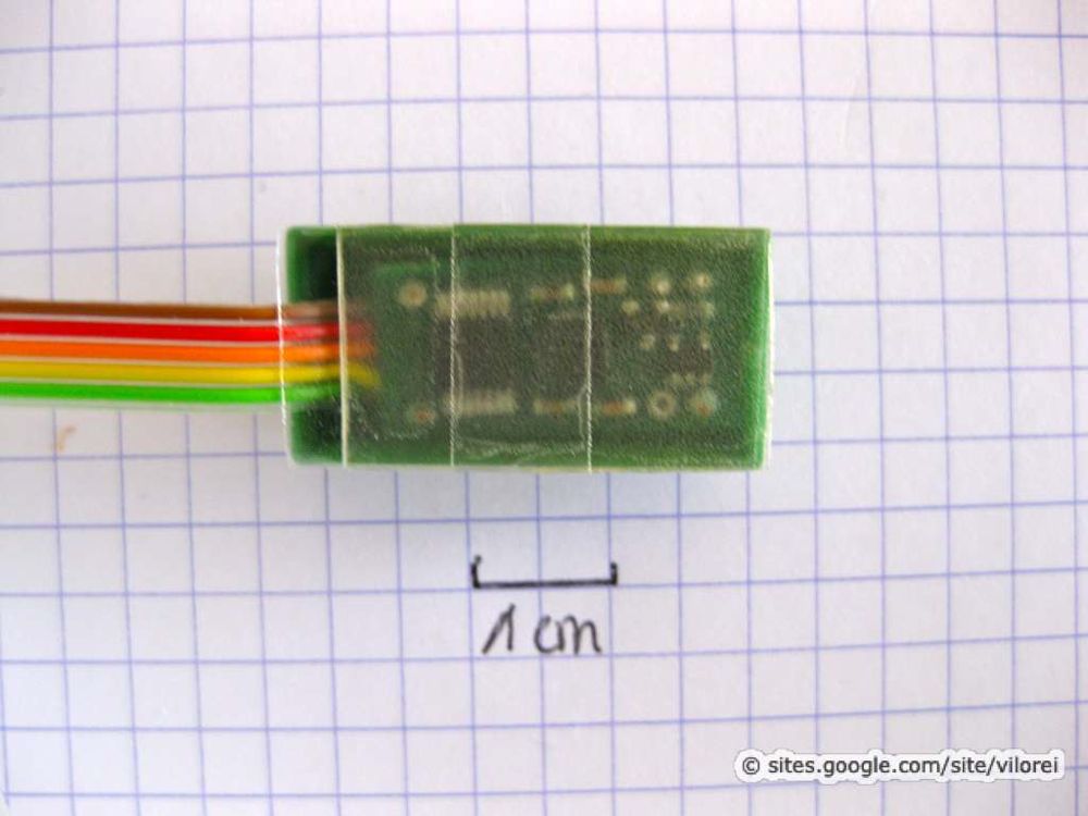
Here's the sensor from Neuhold mentioned on the ft:c forum. The breakboard is supplied without pins, so some soldering is required.
Picture
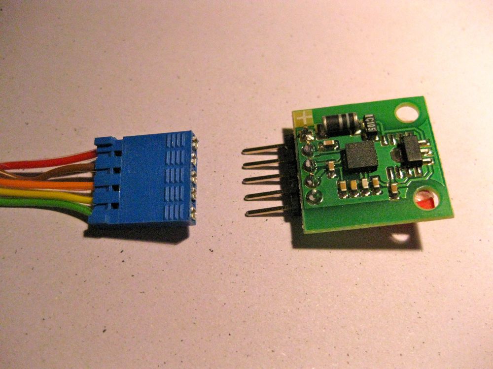
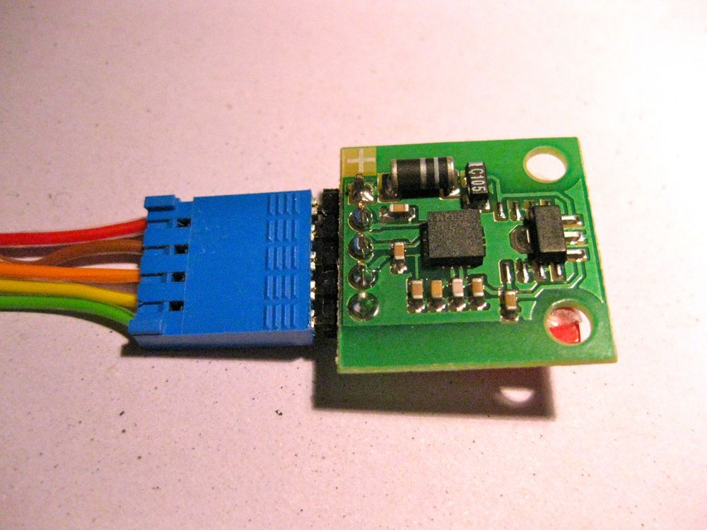
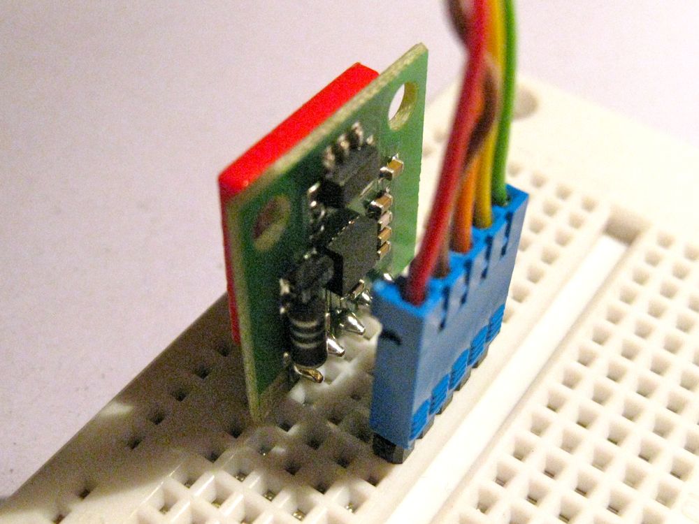
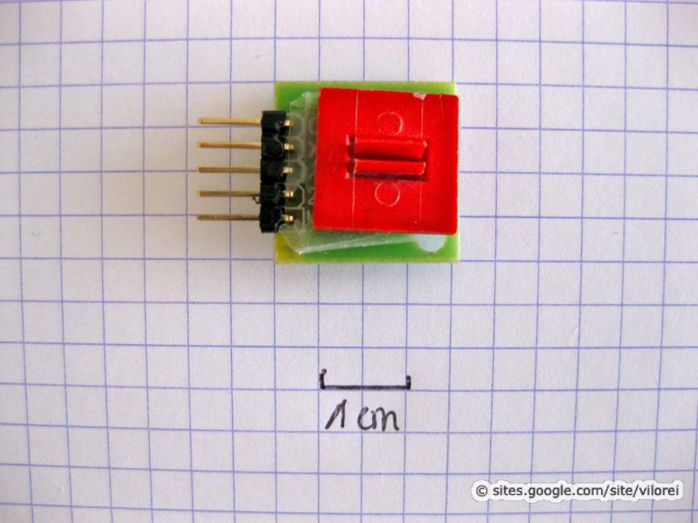
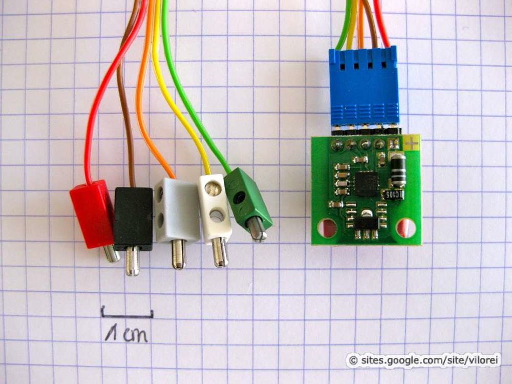
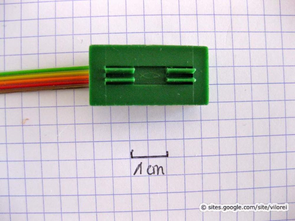
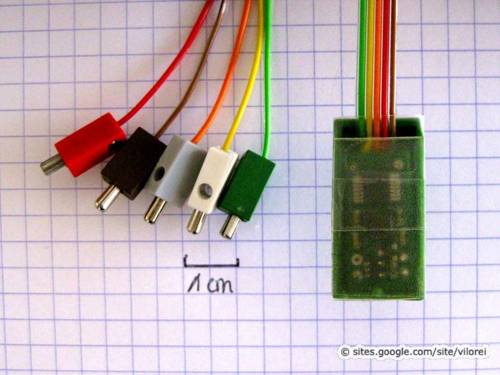
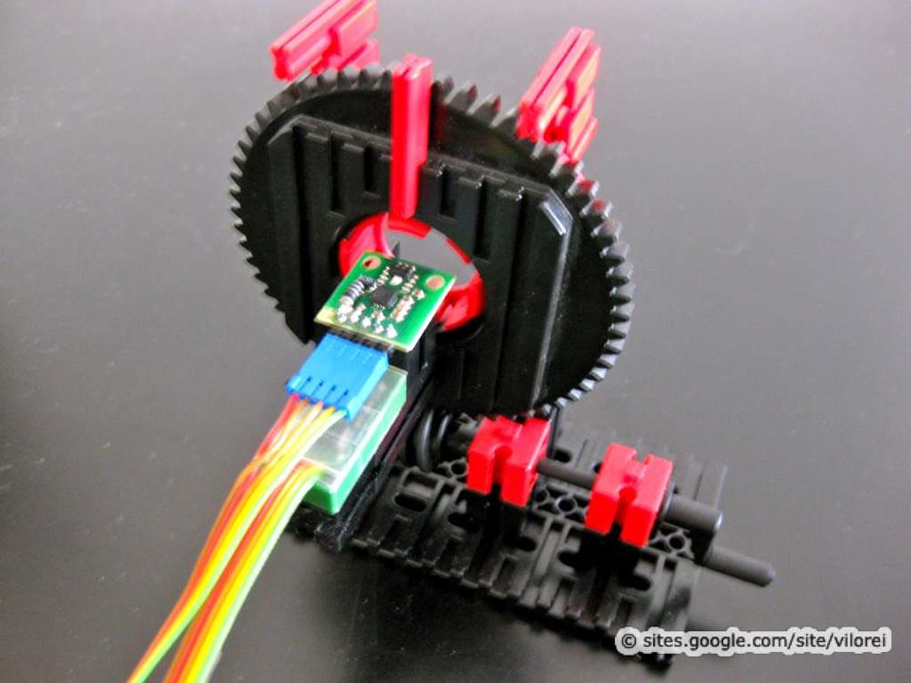
I soldered standard 0,1" HE14 headers and used a nice blue Berg connector (reference). The flat cable ends with 5 fischertechnik plugs.
Picture
Picture
To place the accelerometer on a model, I use duck-tape and a 15x15 red plate (reference 38246). 

Clip-on plate could be even better (reference 31506).
Picture
Picture
The connectors made the use of the accelerometer compatible with a breadboard. 
Picture

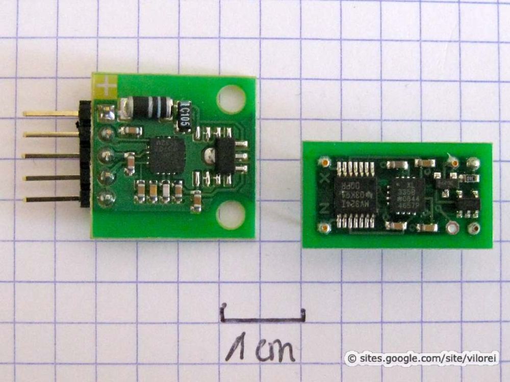
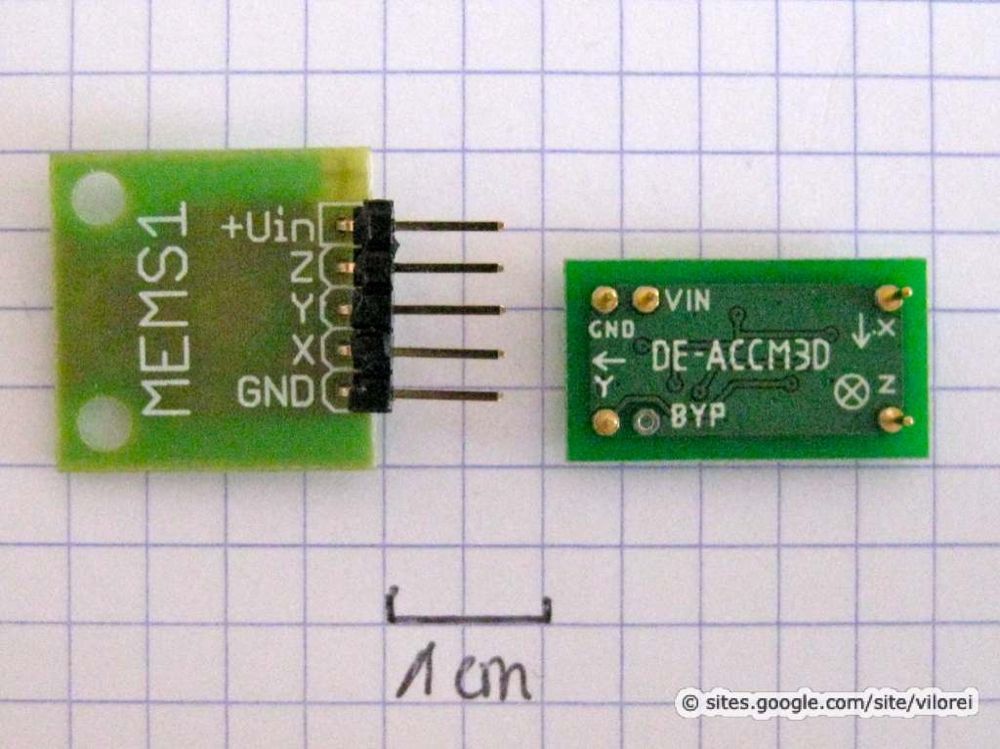
Comparison Between Sensor Implementations

The same accelerometer IC is used is the two break-boards:
  • left: Neuhold
  • right: Dimension Engineering
Picture
Picture
Apart from the voltage regulator and the accelerometer, the Dimension Engineering board includes a third IC, an operational amplifier. 

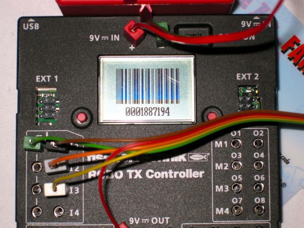
This avoid the nasty bar-code from appearing on the TX controller screen during boot-up.

When the Neuhold accelerometer is connected to the TX controller, the following screen may pop-up when turning the power on.

Here's the detailed explanation I received:
This bar code screen shows the serial number of the ROBO TX Controller. 
This screen shows up if the input I1 detects a resistance of 13 kOhm (+/- 1kOhm) during the start of the controller. 
This is far out of the specified measurement range (0 - 5kOhm). 
So normally this case shouldn't happen if you connect standard ft-sensors to the input I1.
By pressing one of the controller buttons you can return to the normal operation mode.

Picture
How to implement those boards into a fischertechnik model?

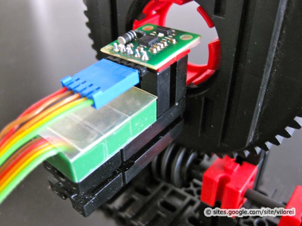
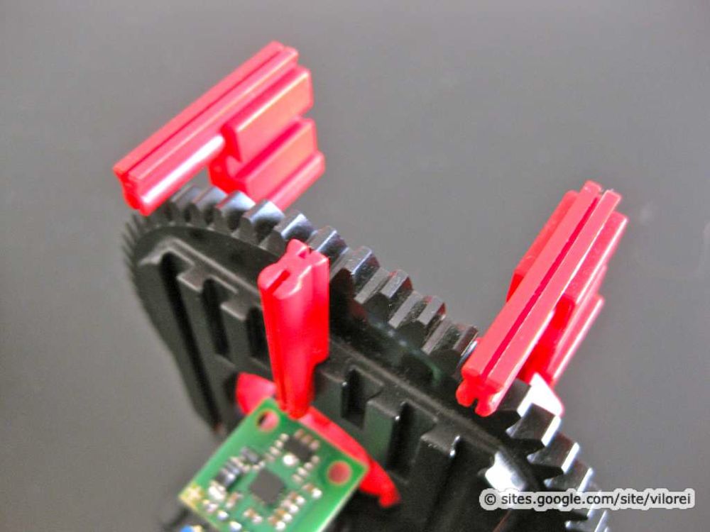
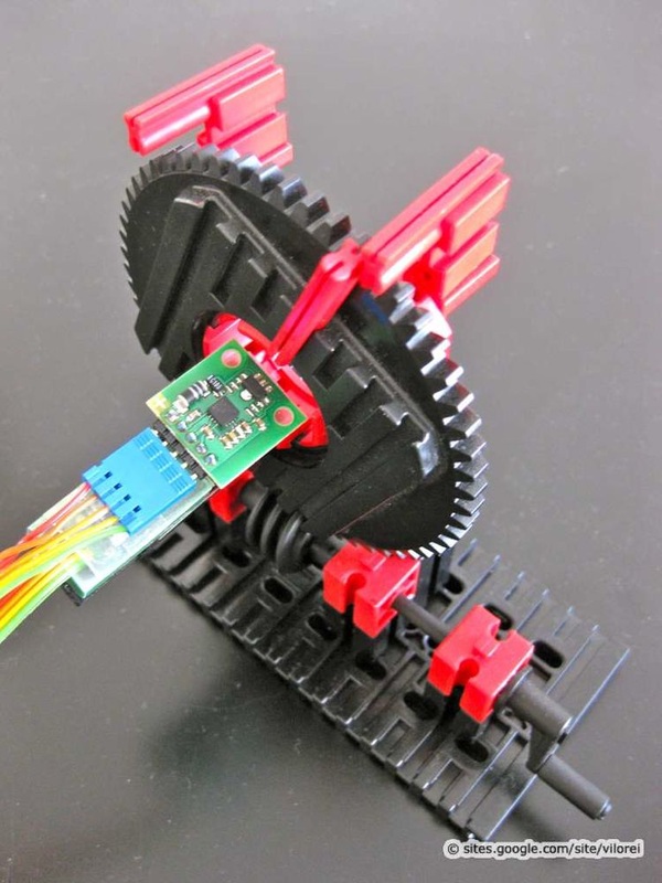
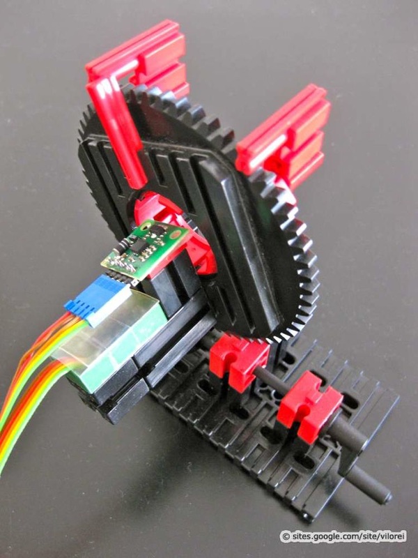
Neuhold Implementation

Picture
Picture
Picture

Dimension Engineering Implementation

Picture
Picture
Picture

Implementations Comparison Protocol

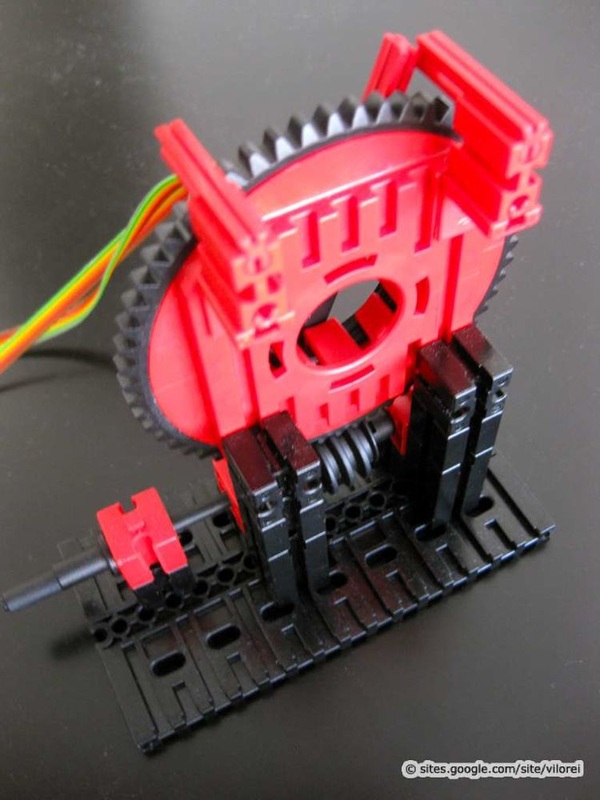
Both are positioned for the test! How do they perform comparatively? Are the measures consistent?

Here is the model I built to test the consistency between the Neuhold and the Dimension Engineering implementations of the accelerometer
Picture
Picture
Picture
Picture
Picture
Picture
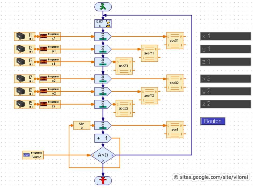
The Robo Pro project is fairly classic, based on the CSV output file.
Picture

Sensor Implementations Results

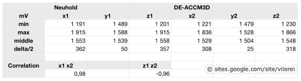
To compare the two implementations of the same sensor, I use the linear model basic correlation coefficient.
  • The closer the coefficient to 0, the worse the correlation.
  • The closer the coefficient to +1 or -1, the better the correlation.
Picture
Results are excellent.

Both implementations of the sensor are consistent.

The y-axis (y1 and y2) wasn't tested on the model, so figures and non significant.

Previous

  • The PID Controller

Next

  • Step-by-Step Setting
Powered by Create your own unique website with customizable templates.